1:20.3 scale, gauge 1 drop-bottom gondola kit
Phil’s Narrow Gauge
1008 Hampshire Lane
Windsor CA 95492
Price: $90, less trucks, couplers, and lettering
Web site: www.philsnarrowgauge.com
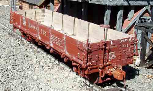
Model of a D&RGW 700-series drop-bottom gondola (#PNG-007); wood kit with metal fittings; trucks, couplers, and lettering not included-can be ordered separately; pictorial and written instructions included
Pros: Well-designed kit of a popular car; pre-cut and drilled parts; pre-assembled frame; thorough, easy-to-follow instructions with many clear photographs; quick assembly; finished car has lots of interesting detail
Cons: Some builders may be uncomfortable with the freehand technique of locating various parts
The materials for this kit consist of precut milled stripwood, laser-cut plywood, steel rods, and white-metal castings. Trucks, couplers, and lettering must be ordered separately: there are several options. Our review sample came with working Accucraft couplers ($5), cast D&RGW trucks ($45), and CDS dry-transfer lettering ($10). There are 21 pages of black-and-white photos plus seven pages of written instructions. I separated the photo section from the text for easier cross-referencing. A model builder with moderate experience may even be able to assemble most of the kit from the photographs alone.
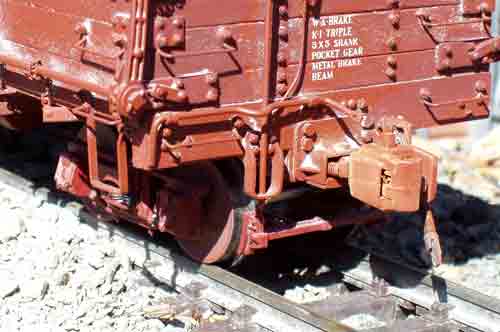
The basic wood underframe comes already built up, so the brake and truss-rod detail can be added right away. Steel nuts are attached to the bolsters by the manufacturer and are mounted so that the truck-mounting screws are perpendicular to the bottom of the bolster surface. Holes are pre-drilled in the brake cylinder, levers, and turnbuckles to accept the various rods. I used Tite-Bond II for the wood-to-wood joints and medium-viscosity CA to attach all of the castings. It has been my experience, when building kits, that you cannot have too many small clamps. Assembly time can be lessened considerably if you do not have to wait for the glue on each part to dry before moving on to the next, which is where all of those clamps come in handy. I treated all of the castings with Blacken-It, so if the paint gets chipped or worn off, no shiny areas will be exposed.
Assembly starts by drilling a few holes to attach some of the parts. Three holes for brake rods go through the needle beams. There wasn’t enough space between the beams for the pin vise and the drill bit, so I wrapped masking tape around the end of the bit to use as a handle. Measurements for locating these holes are not given. The instructions state that you should use figures 2b and 2c to locate these, where the position of the holes are clearly shown. I used the slotted truss-rod holes in the needle beams as reference points. There are other areas in the instructions where parts are positioned by looking at the photos for that particular assembly step. Some modelers may find this lack of measuring disconcerting, but I found that it worked well.
The brake-cylinder and lever support are attached to the frame using brass bolt pins, then the rods and levers are attached. Next, the queenposts and the steel truss rods were added. There were some casting-sprue stubs on some of the queenpost bases I removed with a motor tool. Truss rods ends fit through the plates and are cut flush with the outer faces.
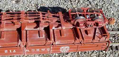
Yokes that support the sides and ends are built up from laminations, then glued in place. Spacers are supplied to properly position the yokes along the frame. The yoke flanges and spacer trim strips then were added.
Because the wood parts are very smooth, the instructions suggest that the corners of the wood used for the floors, sides, and ends be sanded lightly so that the joints show clearly. Since the prototypes did not have painted interiors, I used India ink thinned with alcohol as a wash to give the yokes and boards a light-gray color, which resembles wood exposed to the elements.
The floor, center, side, and end boards were then added to complete the basic box. The addition of several smaller parts finished up the wood work.
There are 28 door braces of various lengths that go on the door bottoms. The floor boards run the full length of the car, so there are no opening individual door sections. No dimensions are given for locating the braces, but one could easily put a brace of each size in the positions shown in the photo, glue them in place, then take measurements to locate the other braces. I used the freehand locating method for the short and long braces near the ends, but used a 1/4″- wide x 1/8″- thick x 2″-long piece of scrap wood as a spacer for marking the location of all of the medium-length braces. I simply put the spacer up against each side of the center-yoke bottoms and drew lines on the floor. I used a wire-brush wheel in a motor tool to remove some of the heavy black patina on the interior corner and the yoke braces before gluing them in place. This leaves the metal looking like it has been worn from heavy usage.
The next step was to mount the chain-roller assemblies, which consist of lengths of steel rod and roller-block castings. These I glued in place on the side boards, then drilled holes through the roller blocks and into the wood. Brass nut-and-bolt pins are glued into the holes to secure the blocks to the car. Details such as the retainer valve, brake staff, grab irons, strap steps, and lift bars were added next.
A 32″-long piece of brass chain is supplied, to be used to attach the door braces to the lifting rods and pin keepers for the arm holders. There are 28 pieces that need to be cut to length and have eye pins attached. The eye pins are glued into the holes in the door braces, then wound over the rods and secured with a drop of CA.
The air hose, angle cock, mounting bracket, glad hand, and supply pipe are pre-assembled by the manufacturer as a unit. This is a time saver, as just one hole needs to be drilled to attach it to the end sill. I mounted the Accucraft couplers with the hex-head screws that come on the mounting flanges rather than with the slotted-head wood screws supplied with the kit. This gives the coupler a more prototypical look. The brake staff and wheel were added to finish up the detail work.
I sprayed the car body and frame with two coats of Krylon Ruddy Brown primer. When the paint was dry I applied the CDS dry-transfer lettering and sealed it with Krylon Matte Finish. A light dusting of gray chalk completed the car.
The finished car has all of the interesting detail and character of the prototype. Several of these would make a nice consist behind a narrow-gauge steam engine or resting near a coal tipple.