What are railroad tower operations? Railroad tower operations can have at least two meanings. One is what happens inside a tower, or more specifically, an interlocking tower. The other is a way of running a railroad, by using the operators in interlocking towers to control traffic through specific points of the railroad. So, why do railroads use towers?
Interlocking tower operations
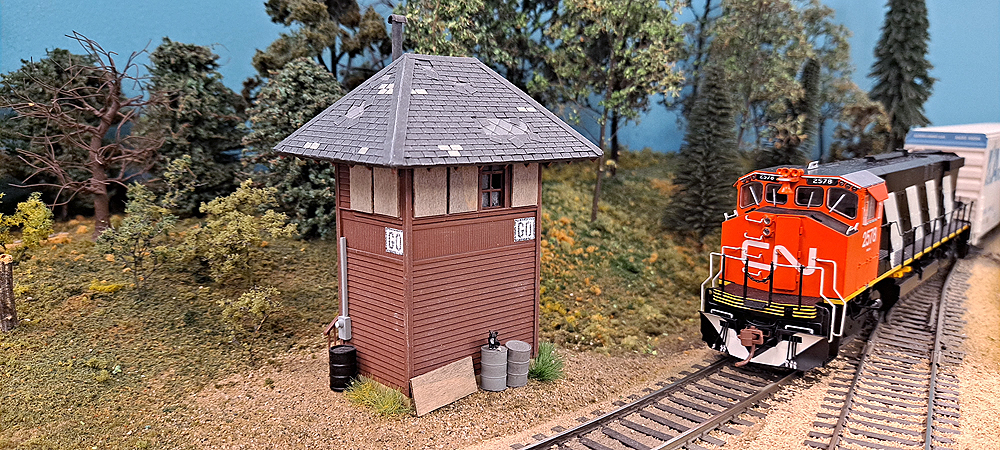
Let’s look at the first one, interlocking operations, as this applies to any railroad that had interlocking towers. An interlocking plant is a junction of tracks. It can be where a branch line leaves the main line, where two railroads cross or intersect, or where turnouts are arranged to move trains from one line to another, such as a crossover between two or more parallel tracks.
The idea is that more than one train is moving through an area where it could potentially collide with another train in motion. The interlocking plant is designed to allow the movement of trains in a safe manner by interconnecting the controls for turnouts and signals so that no conflict can arise that would allow a collision to happen.
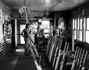
The controls for the interlocking plant are inside the interlocking tower, which is usually a two-story building with the operator working on the second level. Inside are either mechanical levers that are linked by rods and levers to turnouts and signals, or smaller switches and controls linked electrically or pneumatically to the turnouts and signals.
The mechanical lever type, known as an Armstrong plant because it takes strong arms to move the linkages, was the first type built. The linkage is designed so that levers must be moved in a particular order so that a train won’t get a clear signal until the path through the plant is safe. More modern electrical or pneumatic plants have similar fail-safes built in.
As the mechanical plants were replaced by electrical and pneumatic plants, it became apparent that local control wasn’t needed, and many railroads closed their interlocking towers and consolidated control of interlockings in central locations. Today, the control of these plants is handled on computer screens by dispatchers working miles from the action.
Tower operations
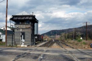
While many interlocking towers began to close down in the 1950s, some railroads continued to staff them well into the 1980s because they were part of the system for controlling traffic on the railroad. This was mostly an Eastern railroad practice. See the article “Life of a railroad tower operator” for a slice of what that job was like.
Operators in the towers would communicate with each other and the dispatcher to monitor the progress of traffic through the system by reporting the passing of trains. On railroads with signal systems, operators would also change signal indications to control the flow of traffic, and signal trains to stop at a tower to receive orders. Even when radios began to be installed in locomotives and cabooses, many railroads continued the practice of writing and delivering written orders to ensure the message was received.
Applying tower operations to a model railroad
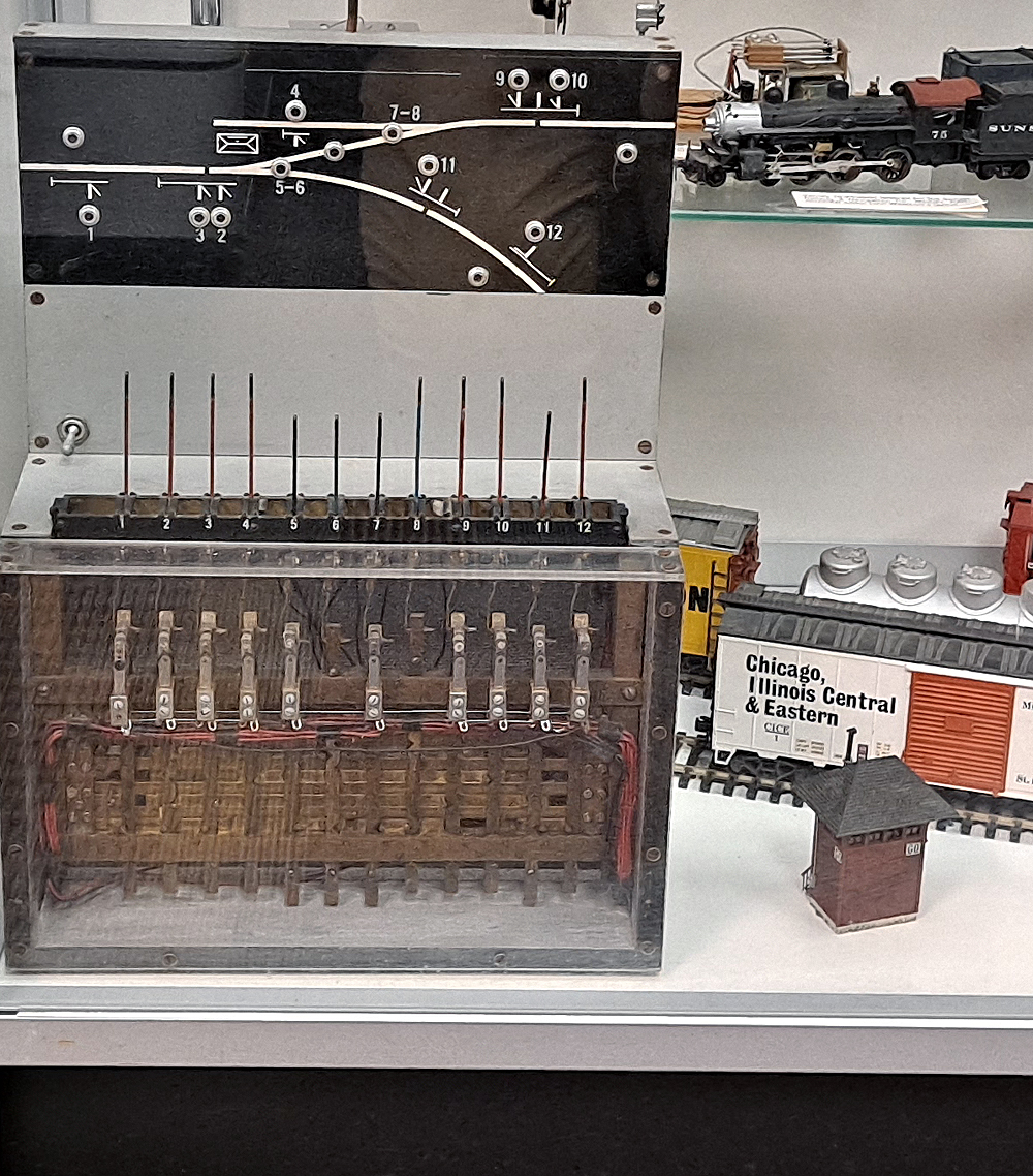
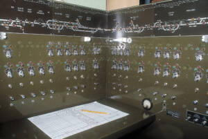
Both types of tower operation can be added to a model railroad. The first type, operating an interlocking plant, can be accomplished by modeling the controls and switches on a panel situated in the layout room. Model Railroader associate editor Gordon Odegard built an operating Armstrong-style control panel complete with mechanical interlocking in the January through March 1961 issues. More recently, people have made panels using CTC knobs from suppliers such as Rix and Mike Burgett’s and Alan Bell’s Control Train Components, computer-based systems built on the Java Model Railroad Interface’s PanelPro, and simplified mechanical interlockings using homemade levers or the long-discontinued Humpyard Purveyance levers.
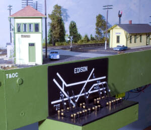
Simulating tower operations on a model railroad is an interesting variation that combines the jobs of an operator who writes and delivers trains orders with that of the interlocking tower employee who lines turnouts and sets signals. Bill Neale re-created this system on his Pennsylvania RR Panhandle layout. One person held the job, Mark Steenwyk on the session I joined, and while it wasn’t his first choice, he enjoyed the job. It would require a fairly large layout to simulate the handing off of trains from tower to tower, but it’s certainly an intriguing possibility.
Both types of tower operations would be fun to add to a model railroad. Maybe one would be right for you.


