Editor’s note: This manuscript was purchased in December 1990 for Model Railroader magazine. Over the years, it made its way around the office and finally landed in my hands last fall. Dave Ingles was a friend of mine, and with his passing and my becoming editor of CTT, it seemed fitting to finally share his text. His friend Mike Schafer provided text too, but sadly the old floppy disk in the folder had gone corrupt and I had no hard copy to scan. He did provide the photos and illustrations.
No matter if you run Flyer, Marx, Lionel or some other scale, I hope you enjoy this article. I think it’s just plain fun.
In 1953, a box of American Flyer straight track under the Christmas tree was nirvana. It meant that a circle of track, one No. 302AC Atlantic, and three cars received the previous Christmas could be expanded to unimaginable (to a five-year old, anyway) proportions.
The addition of an American Flyer El Capitan set in 1956, plus a set of manual switches, elevated my Flyer system to new heights. For all of you who began your electric-train careers this way — as kids who got trains and accessories for Christmas, birthdays, etc. and then expanded from there — you know how the story goes.
The Flyer became a familiar fixture on my bedroom floor, but by the time I was about 12 and had accumulated a respectable amount of track, I got the idea to lay main line into uncharted territory. In a bold move one day when Ma wasn’t home, the main line found its way into the kitchen, dining room, and living room. It was a hit with the neighborhood kids, and my mom turned out to be rather tolerant of it.
Alas, shortly thereafter the Flyer was relegated to a new table in the basement. Although this gave me complete freedom with things like permanent scenery and decent wiring, it rather limited having a lengthy main line, which was something I really yearned for. But this was moot, as I made the big switch to HO scale modeling railroading in 1963. The Flyer was packed away forever … or so I thought.
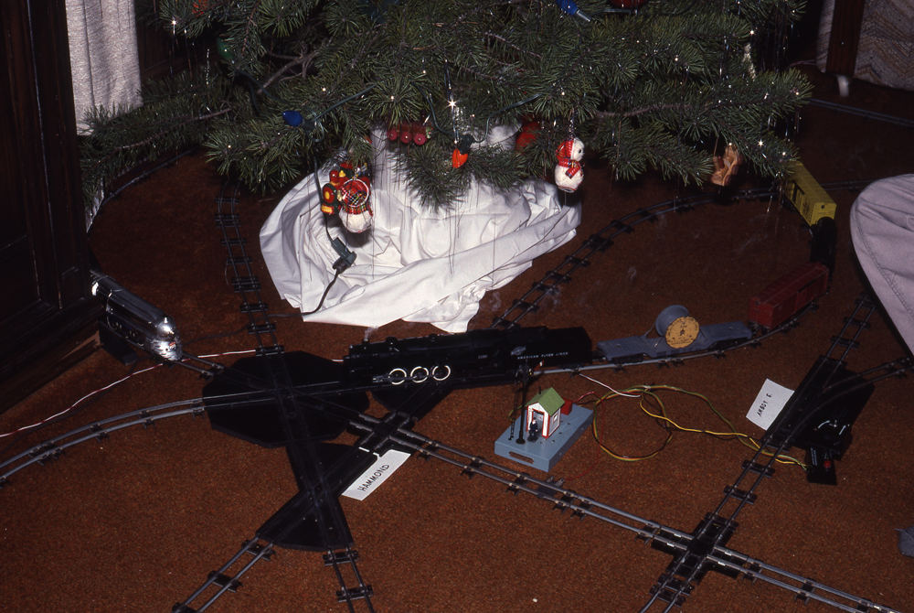
By the 1980s, Flyer (and Lionel and Marx) had become a classic. Despite my ties to scale model railroading, the “Classic Toy Train” bug bit me in 1985, and I again began collecting Flyer and reconditioning my original equipment. About this time, the bug had also bitten friends of mine, Mike and Judy McBride, and their teenage sons Andrew and Chris. Mike was also a “lifer” in model railroading.
The inevitable happened. Mike and I concluded that when it came to operating American Flyer, two collections were better than one. Thus was born the “Super Layout,” or what we sometimes refer to as McBride & Sons, Barnum & Schafer American Flyer (Rail) Road Show.
In short, a Super Layout is one where (always on the floor, of course) we create the biggest railroad we can in the space available for the operation of at least four trains simultaneously. Now, if that’s all there was to the story, you could go on to the next CTT feature. But as Mike and I discovered, assembling a large operating Flyer layout presents some challenges. For those of you into operating your toy trains, we have some suggestions so that you won’t have to reinvent the (flanged) wheel.
Overall concept and approach
The most manageable way to do a Super Layout is to build a large single-track main line with passing sidings, each of which needs to be only long enough to accommodate, say, a 7-10 car freight train or passenger train of equivalent length (long trains are not recommended here). The idea is to send trains around the layout, with opposing trains meeting each other at passing sidings and, occasionally, faster trains overtaking slower ones.
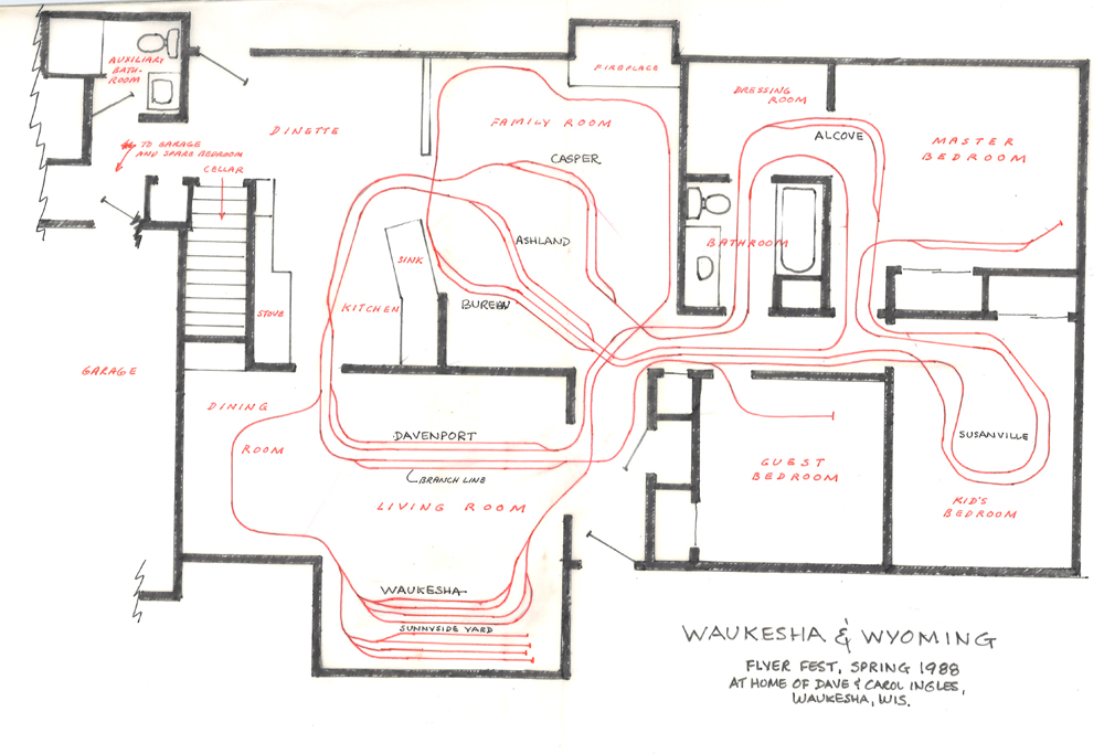
Avoid track plans that call for numerous short cuts, alternate routes, and reverse loops, which only add to the logistical nightmare of keeping track of trains, to say nothing of the wiring. Nonetheless, how you fold a main line to fit the given space is quite another matter. Ponder the track plans shown, and you’ll see that your imagination (and the confines of the space you’re working in) are the only limits. Follow the main line in each of those plans and you’ll see that it’s indeed essentially just a continuous circle.
Because of the temporary nature of this kind of operation, we determined it to be unfeasible to “block” the track into sections that could be individually controlled via toggle switches. The wiring becomes far too complicated and time-consuming. Rather, all trains operate from one power source and throttle; trains are stopped individually by having both switches thrown against the train while it is at a passing location.
Surveying the main line route
Between us, the McBrides and I have some 1,000 sections of track, nearly all of it purchased at local train shows and flea markets. Even if the track you find is pretty beat up, sanding the rust off the rails and replacing the pins is a task you can mindlessly do while watching television. And if you’ve got sections that are really beat, you can always cut the usable portions of them into oddball lengths, which, believe me, you’ll need plenty of. Not only do we use generous numbers of half-straights and curves, but also three-quarter lengths and sections as short as an inch.
Securing right-of-way may be a little trickier, since it requires not only a sympathetic property owner, but also a level floor. Ideally, Mike and I like to work in a house that has a “circular” floor plan; i.e., that where rooms are linked by more than one entrance. Neither Mike and Judy nor I have houses that fit that bill, but this isn’t a big deterrent. We’ve still managed to do some pretty wild layouts in our homes, and a number of friends who have become fascinated by our Flyer-on-the-floor bit have opened up their own larger homes for weekend road shows.
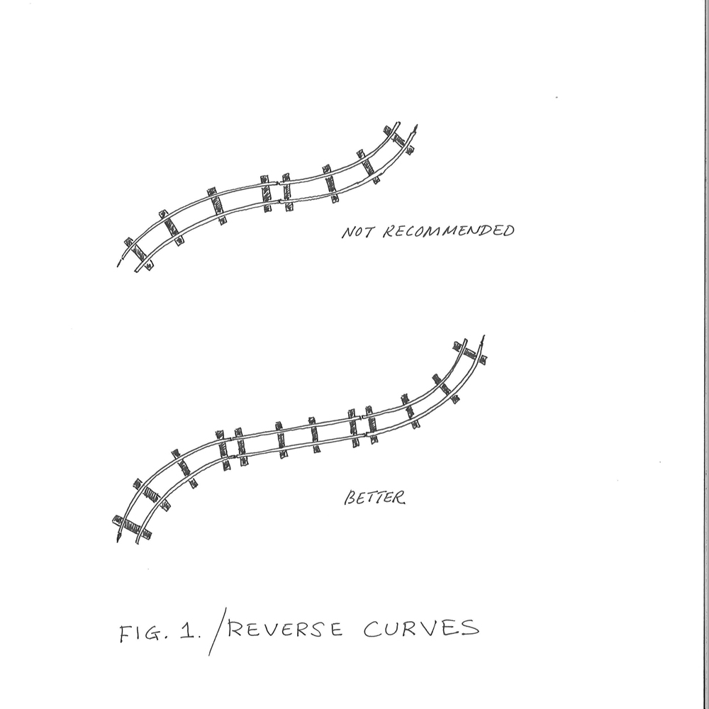
Setup time runs in the neighborhood of seven hours. One of us usually makes a rough sketch of the intended track plan, which always gets modified as construction progresses. Important: Check the track plan early on for possible hidden reverse loops. Inspect each section of track for defects, especially for rails that have been bent vertically (usually from being stepped on), even slightly. Most important: Not only must the railheads be clean for good electrical contact, but also each track pin should be bent outward slightly.
- Assemble the most complex segments first.
- Allow track to lay naturally. Do not force-fit an arrangement, especially where it will result in an outward kink on a curve.
- Wherever possible, avoid reverse curves; instead, insert at least a half section of straight between the two curves. Trains will track better, especially long-wheelbase locomotives and rolling stock.
- If you have it, use rubber roadbed where track is laid on tile floor.
- If you have thresholds or other uneven floor situations to cross, shim the track to make the approaches gradual and minimize “peaking” at track joints.
We usually have a fairly good idea of where we want to locate passing tracks before we begin laying track, but sometimes we add one or two after the main line has been put down. Passing tracks should be spaced fairly evenly apart; for example, if you have a 200-foot main line with four sidings, aim to have one about every 50 feet. The idea is to have one person assigned to operate each siding, though if you position two sidings near one another not by mainline distance, but by location, one person can operate both.
Most Flyer switches have a power route option button, and this is the key to making Super Layouts work. Set in the REGULAR position, power goes to both routes; set for TWO-TRAIN OPERATION, power goes only to the route for which the switch is aligned. (“Two-train operation” is sort of a misnomer; it really means “multiple-train” operation — two, three, four or more trains.) Later Flyer switches do not have this button, but fortunately were built with the two-train option. When both switches are thrown against a train within passing-track boundaries, the train halts. It remains stopped until the opposing train has passed (a “meet” in prototype parlance), or a faster train going in the same direction has run around. When one or both of the switches are thrown back, the halted train resumes its run.
Powering the Super Layout
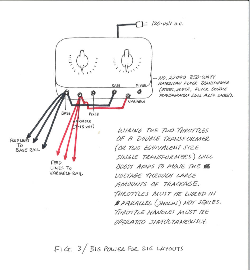
Whenever possible, we prefer remote-control switches. Remote-control switches should be run from a separate transformer; the main transformer will need all its juice for running trains.
Getting proper power to the tracks proved to be one of the biggest stumbling blocks of operating a Super Layout. In our earliest layouts, we simply hooked the biggest transformer either of us had — a 100-watt single throttle — to the tracks. We knew that feeder or bus wires were a must to alleviate voltage drops at the far reaches of the layout, and thus incorporated them from the very start.
Nonetheless, we could usually only get two trains to successfully make a circuit without significantly slowing down somewhere. The trains had to be short and light; lighted passenger cars and action cabooses were out because of the drain on power.
When operating trains with this arrangement, both throttle dials must be turned at the same time and pretty much the same amount. To turn one throttle on a mite and the other all the way will blow the circuit breaker, since the throttle that’s only partly on becomes, in essence, a resistor that’s damming the current. Obviously, this two-transformer arrangement requires two hands, but it’s easier than it sounds.
Things improved when Mike got a dual-throttle transformer, one of those 300- watt (No. 30B, later No. 22080) jobs we could only dream about owning as kids. Although this significantly solved the overall power-distribution problem, we did one better when Mike then purchased a late-model No. 22090 350-watt transformer. We have yet to build a layout large enough to tax that one.
Our November 1989 operation featured a 700-foot main line with up to six trains, some of them with double-headed locomotives or twin-motor diesels and lighted cars. There were no power drops except at one corner of the layout. There we put in a “booster pack,” a 35-watt No. 1 transformer that we wired to the tracks at the weak spot and pretty much left on at full-throttle, unattended. Except within about 40 feet of where it was attached, it did not push enough power into the layout to interfere with what the main transformer was doing.
More about those all-important feeders: Be sure that all feeders originating at the base post indeed go to the base-post rail, and those originating at the variable (7-15 volt) post go to the other. This may seem like an overly basic warning, but on a large layout that’s quite contorted, it’s easy to lose track (pun intended again) of which is the base and which is the variable rail. Likewise, on a large layout, a clash in polarity resulting from crossed feeders is not always readily apparent. If you place a test locomotive on the track near the transformer’s main feed line, it may actually run part way around the layout until it gets into the zone that’s being fed opposing polarity. Only then will the locomotive slow down and the circuit breakers go off.
Use heavy-gauge wire for feeders, and feeders should go directly from track terminals to the transformer, not to other nearby track terminals. IMPORTANT: Do not attach any feeders within the boundaries of passing-track locations.
Gentlemen, start your engines
If you’ve got the track up and feeders are all in place, it’s time for test runs. Rarely have we had a test train make it all the way around the layout for the first time without some sort of mishap. There’s always a stage where you must troubleshoot and fine-tune things before the big show gets underway.
Once you get a locomotive and perhaps a short train to run completely around the layout without any problems, then go to a “regulation-size” train. Allow it to make a couple of trips around the entire layout on all the different trackage. If a locomotive or car derails, it does so for a reason. If a derailment occurs at the same spot more than once, and particularly if different equipment has a problem at the same location, then you can bet you have a track problem, usually a bent rail. Even a subtly bent rail can be a trouble-maker.
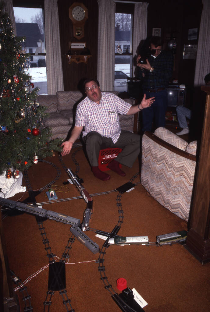
We also made some other discoveries. For example, Flyer steam locomotives, especially Atlantics (4-4-2s) and Pacifics (4-6-2s), in general track better and operate more reliably than do Flyer diesels, so most of our trains are steam powered, despite us being ardent diesel fans. Besides, we’re all hooked on the smell of Flyer smoke. Also, be sure that the powered truck on bidirectional locomotives such as the GP7 and the New Haven EP5 electric (A.F. 455) is leading.
Before an operating session, oil all equipment, especially locomotive bearings, and fill smoke units. Replace locomotives from time to time during operating sessions so they can cool down. We’ve discovered, for example, that the field on Flyer GP7 motors tends to lose its magnetism after extended periods of operation, resulting in a temporary loss of power.
By far, the biggest problem we have is usually with couplers, and it doesn’t matter if they’re link or knuckle. “Break-in-two’s” are frustratingly common sometimes, and they always happen behind the couch or in the other room where nobody is watching. Any rough or uneven track can make a car bounce and bump the knuckle-release bar. If a particular car seems to be having problems staying coupled, check to see if the coupler is broken or sagging. Here’s a trick for a knuckle coupler that likes to open frequently: Wrap a short piece of bell wire around the stem to prevent the release bar from being pushed up.
When assembling trains for the operating session, place the heaviest cars at the front of the train. Invariably, some locomotives run just too fast, and since an operating session usually requires full-throttle operation, you’ll need to slow those down by including some extra-heavy cars-such as an operating boxcar or some of those heavy cast-metal cars-in the train.
Dispatching
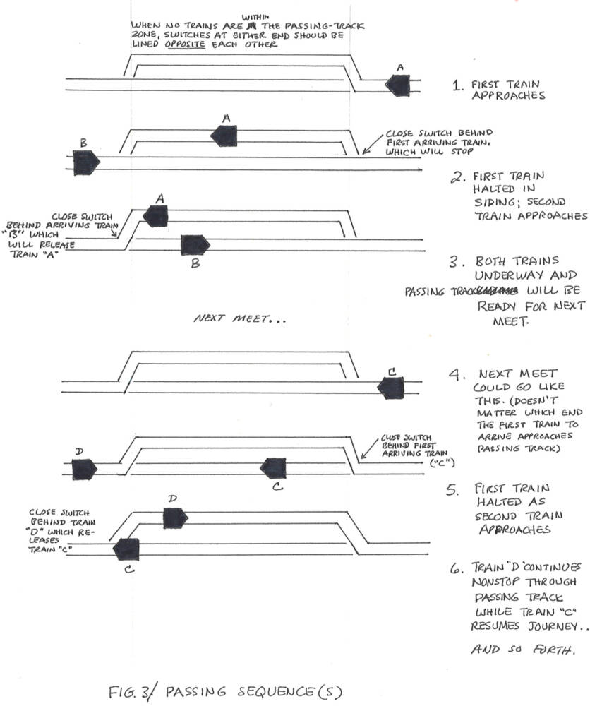
Basically there are two methods for dispatching trains on a Super Layout, “hard” and automatic. Hard dispatching mimics that of a prototype railroad. Each “tower” operator reports the presence of a train at his or her siding to the dispatcher, who makes note of each train’s progress. The dispatcher then determines where opposing trains are going to meet each other and directs the appropriate tower operator to set up a meet. This method requires a drawing or schematic of the track plan upon which the dispatcher can keep track of trains.
We use M&Ms as markers — a red one for a Pennsy-powered train, a green one for the Rocket streamliner, etc. This works great until the dispatcher gets hungry. Hard dispatching works best on large layouts where sidings are far apart; on small layouts with main lines of 400 feet or less, things tend to happen too fast for the dispatcher to properly keep track.
With automatic dispatching, you can fire the dispatcher. Trains are put into a sequence whereby every train meets an opposing train at every passing location. For automatic dispatching to work, there has to be one siding for every train being operated. If you have three trains, you’ll need three sidings; six trains, you’ll need six sidings. If you have four trains and five sidings, simply do not use one siding.
With TWO opposing trains, two sidings: Start both trains at the same siding.
With THREE trains, three sidings: Start the two opposing trains at any siding and the third train, regardless of its direction of travel, at either of the two remaining sidings.
With FOUR trains (two in each direction), four sidings: Begin with two opposing trains at each of opposite sidings; there should be an empty siding between the two full sidings.
With FIVE trains, five sidings: Begin with two opposing trains at each of two sidings separated by one empty siding; the fifth train should be positioned at either of the other two sidings and must face the nearest siding that has two trains meeting and must face those two trains.
With SIX trains, six sidings: Begin with two opposing trains meeting at a siding; the next siding (either direction down the line; it doesn’t matter) should have only one train, but it must face the siding that has the two trains; the third siding should be completely empty; the fourth siding should have two opposing trains; the fifth siding should have one train facing the fourth siding; and the sixth siding should be empty.
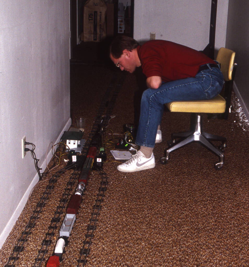
Once things are underway, meets at passing locations can be performed with ease if you follow this simple rule: Throw only the switch behind the arriving train.
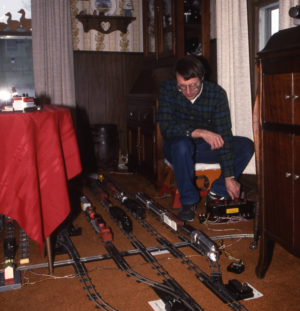
Here’s how it works: At an empty passing location, the switches at either end should be thrown opposite of each other. When the first train gets entirely within the passing section, throw only the switch that’s behind it, and the train will stop. Then, when the opposing train gets into the passing location, thow only the switch behind its last car and the train that had been sitting will restart; the opposing train will keep going. Once both trains have cleared the passing location, do not throw any switches back. You are already set for the next meet.
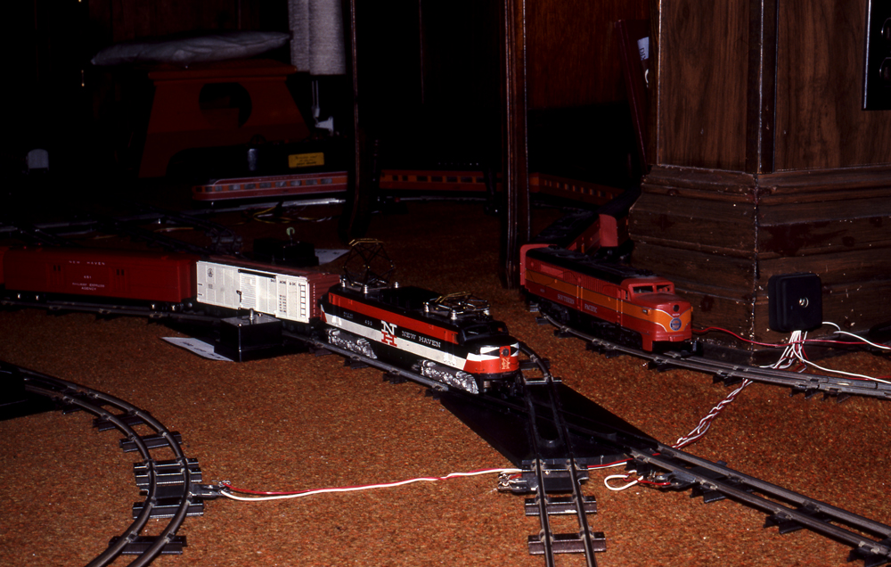
Once you have the meeting procedure down to a science, you’ll be able to concentrate on some of the other challenges of operation, mainly preventing collisions at crossings. You’ll soon note that some crossings are more collision-prone than others. Since we are dealing with collectibles, you’ll want to protect these crossings or “diamonds” in some manner. The best way to do this is with a Sam the Semaphore Man, or an “interlocking” arrangement that lets only one train through a crossing at a time. A simple single-pole double-throw toggle switch wired into dead-block sections will also work well.
Operation is now underway, and you and your guests will have hours of fun. Which is what Alfred C. Gilbert wanted.
More about Mike Schafer:
https://www.trains.com/ctr/railroad-stories/railfan/for-mike-schafer-theres-always-a-shot/
More about J. David Ingles: https://www.trains.com/trn/news-reviews/news-wire/j-david-ingles-former-trains-editor-and-47-year-kalmbach-staffer-dies/


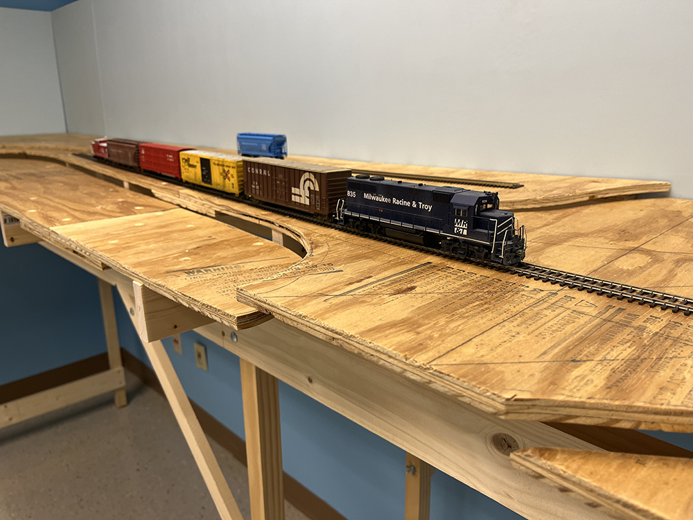
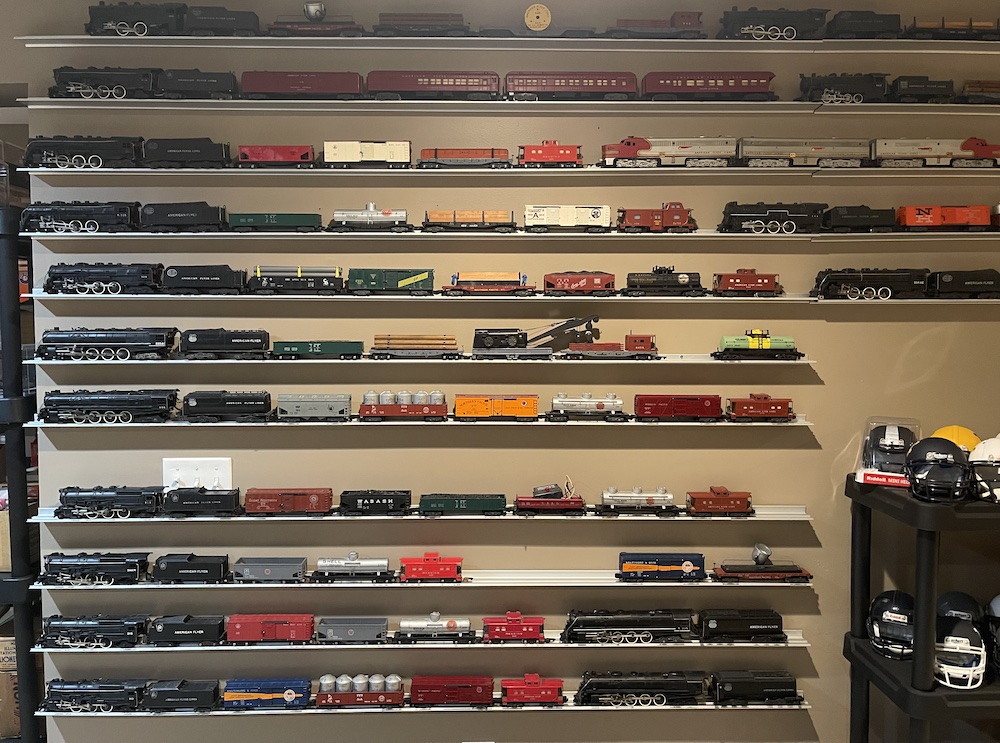

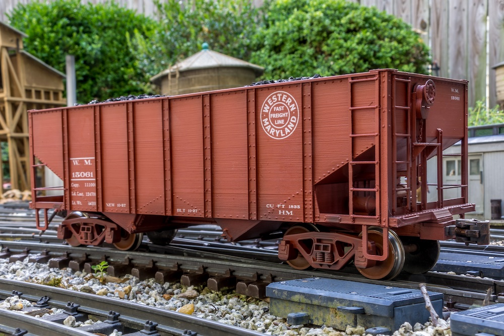


My dad bought a “Flyer” set for my brother and me when we were about 7 or 8. I had a New York Central steam engine and a nice string of cars. The track was just an oval but we also had two powered switches so we could create a siding. The set eventually found its way onto a 4X8′ sheet of plywood and lived in the garage, leaning up against a wall so the car could squeeze in too. None of my friends had train sets so the option of having a “super layout” was pretty much out of the question, but we (I think I more than my brother) enjoyed running the train. I went on to join a couple of model railroad clubs, both in HO scale, but the one I belong to now (started in the late 40’s) originally ran a 3 scale (Lionel, Flyer and HO) layout that my dad, my brother and I visited maybe before we got our own Flyer. I thought it was pretty cool. That layout was dismantled in 2012 and a new 2 deck, DCC layout was built. I still have our Flyer set and would like to get it all out again some day to run around.
Impressive and jaw-dropping.