How To Expert Tips Control a working display case

Control a working display case

By Randy Bartlet | October 4, 2024

Continue the project started in our October 2024 issue

Email Newsletter

Get the newest photos, videos, stories, and more from Trains.com brands. Sign-up for email today!

This project is the continuation of the “Build a working display case” project in our October 2024 issue. This second part details the physical and software infrastructure Randy built to control his working display case using an Arduino Nano.

The working part

All my locomotives are Digital Command Control, and most have sound. It’s obviously not desirable to have all the sound-equipped engines running every time the layout is turned on, or even when I want to move just one of them. So I designed turnout switches that power each track only when the turnouts are lined for that route.

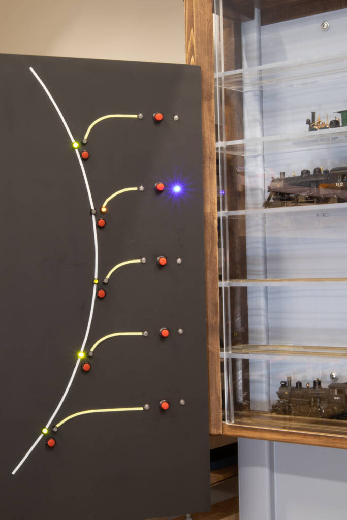
A black board with lines, lights, and buttons next to a display case
Randy’s fascia control panel shows that he has two turnouts for each shelf. The mainline turnout (left) routes trains onto the display when lined. Then the turnout (right) routes trains to either the front or back track on the display shelf.


Turnout switch wiring

The wiring diagram below shows how the turnout switches are wired to provide power to the desired track. The black and red rails are always powered. The mainline turnout switch (left) shows the frog being powered (green) as you’d expect. But notice that the orange rail beyond the frog is also powered to match the frog. This means that when the turnout is closed (routed for the mainline/helix), the orange rail for the frog and display case has the same polarity as the black rail. When the black and orange rails have matching polarity, there’s no power to the shelf.

But when the mainline turnout is lined for the display, the orange rail has the same polarity as the red rail, thus providing power. In this position the back rail of the back track (orange) always has the same polarity as the red rail. It’s the two center rails (gray front rail of the back track and blue back rail of the front track) that require special power switching.

Now look at the front/back turnout double-pole double-throw (DPDT) switch on the right. I wasn’t able to find a DPDT micro switch, so I stacked two single-pole double-throw (SPDT) switches together. The result is the same as a DPDT. Think of the top switch as input and the bottom switch as output. The top switch determines the polarity of the common post and powers the frog. This common is also directly connected to the common of the bottom switch.

The bottom switch, then, determines which of the two center rails gets that polarity. If the turnout is lined for the back track, then common (green) will have the same polarity as the black rail, as will the front rail of the back track (gray/white). I used white wire, but I depicted it as gray in the diagram for clarity. At the same time, the back rail of the front track (blue) will have no polarity. And when the turnout is lined to the front track, the blue rail will have the same polarity as the red rail; the gray rail gets no polarity.


Turnout motor mount

When I started laying track, I used Walthers turnouts because of its easy-to-connect push buttons and light-emitting diodes (LEDs). But I soon realized that I’d need a less-expensive way to power all the turnouts on my layout. I purchased SG90 servo motors and micro limit switches, both of which are easy to source online.

I found on Thingiverse a 3-D printable SG90 servo bracket called “Servo Turnout Motor for Model Railroads”. I’ll call it the servo mount. The mount consists of a base and a left-handed or right-handed cap.

The servo motor can be attached to the mount base either in a left position or a right position. Choose the position that works best for your turnout. I used the right.

A servo mounted on a piece of wood
The servo motor mounted on the base in the left position.
A servo mounted on a piece of wood
The servo motor mounted on the base in the right position.
A servo mounted on a piece of wood
The servo motor mounted with its cap in the normal (right) position as designed.

But I attached the left cap instead, and backwards. I should explain this unusual configuration. I needed to attach three micro switches — the two described above plus one for feedback to indicate the current position of the turnout.

A servo mounted on a piece of wood
Randy attached the left cap in the backwards position with the servo mounted to the right.
A servo mounted on a piece of wood with micro switches attached
The final configuration of the servo adds three micro switches to the setup.

I stacked two switches together on one side and the feedback switch on the other side. When the motor presses against the two switches at once there is a greater resistance by the switch arms. This forced the motor to keep pushing against the arms, causing a significant hum. And it would definitely have caused the motor to burn out before too long. I needed to lengthen the switch arms because the farther away from the arm’s fulcrum, the less torque is needed to hold the switches.

I added a piece of plastic to the end of each switch arm (light blue in the above image). But I had to move the switches farther from the servo motor horn so the horn would press against the end of the arm extension. After some experimentation, I discovered an easy way to do this. I used a left mount cap instead of a right one and I attached it backwards onto the mount base. This allows the micro switches to be attached to the cap’s pre-formed holes, but farther away from the motor horn.

If you have access to a 3-D printer to print the motor bracket, then you can also print my 3-D micro switch extension. It slips onto the end of the switch arm. If it fits too loosely, just apply a drop of hot glue.

Each servo motor comes with several horns of varying lengths. Because of my unusual configuration, I needed as long a horn as possible. I used the horn with four posts, the longest of these posts has seven holes. I removed the other three posts. But even this wasn’t long enough. I attached a piece of styrene tubing to the end of the horn. The horn material looked like it wouldn’t accept most glues, so I used hot glue. I made the tubing long enough that it would easily press against the extended arms of the two stacked switches. I was careful that the glue didn’t interfere with the turnout switch rod.


Fascia wiring

The final turnout switch machine, including wire connections, looks like the photo shown below. You’ll notice that I have added three extra wires to the top micro switch. These are connected to the fascia LEDs. The wires to the upper-left of the photo are from the DCC bus, those to the bottom go to the display rails, and those to the upper-right connect to the fascia LEDs.

Multiple colored wires attached to a servo motor under a train layout
The switch is wired so that the red and black wires are the DCC bus; the white, light blue, and green wires on the bottom go to the display rails; and the light blue, yellow, and green wires on the top connect to the fascia LEDs.
Wires and connectors on a white wall
Here is the back of the fascia. The devices on the right are Walthers turnout fascia controls. They’re connected to the mainline turnouts on the helix.

The wiring for my servo controllers looks more complicated than it actually is. Since I need to be able to disconnect the layout from the display case — and because the facia is connected to the display case (with piano hinges) — I added a connector for each wire. I know that many have touted the suitcase connectors for layout wiring, but I find lever-nut connectors from Wago much more convenient. I can easily disconnect and reconnect wires as needed. And I’ve already had several occasions where this saved me in time and effort. I glued the connectors to the fascia with hot glue.

Two wire connectors on a wood surface
These lever-nut connectors from Wago are convenient for layout wiring, enabling disconnecting and reconnecting wires repeatedly.
Wires and connectors with a callout to a 2K ohm resistor
In this closeup of one shelf’s facia controller, the push button is in the center and the LEDs are to its right and left.

The push button is connected as an input to an Arduino Nano which controls the servo motor. The three connectors on the bottom are connected to the yellow, green, and blue wires in the top of the switch. They power the two LEDs. Notice the resistor in the center. It’s connected to the micro switch green common wire and to the cathode (short) pin of each LED.

My LEDs are rated 3-3.2 volts and 20 mA. My research showed that I’d need a 1K ohm resistor. However, my LEDs kept burning up. I switched to a 2K resistor and the problem went away. I’ll have to wait to see how well the LEDs hold up. If any burn out, I will try adding a 1N4001 diode in reverse parallel with some LEDs to see if they last longer than those without the extra diode. But the LEDs are only on when the main turnout is lined, so they won’t get used that much.


Arduino Nano controller

The Arduino Nano is a small and inexpensive, but very capable, controller featuring 30 pins. Some of the pins are for dedicated purposes like power in, power out, ground, and others. Eight of the pins are labeled “A” for analog, and 12 are labeled “D” for digital.

A blue circuit board with USB attachment on left side
The label side of the Arduino Nano.
A blue circuit board with USB cable attached on left side
The pin side of the Arduino Nano.

Arduino documentation says that six of the digital pins can be used to send pulse width modulation (PWM) signals. Those six pins are labeled: D3, D5, D6, D9, D10, and D11.

The SG90 servo motor uses PWM signals to move its horn to specified positions. Any of the digital pins and analog pins can be used as digital inputs. It’s really the software that dictates whether a pin is input or output. But you can’t just use any pin for any purpose. The Nano (and other Arduino boards) have built-in electronics that give some pins special capabilities and others not. The six PWM pins are a good example of this.

I have five working shelves. Each shelf needs one PWM output to control the front/back servo motor, one digital input to monitor the pressing of the fascia push button, and one digital input to get the current position of the turnout (feedback). The push button and feedback inputs can use any of the remaining digital or analog pins on the Nano.

Arduino Nano laying on its side with wires connected to the back
The digital side connections of the Arduino Nano.
Arduino Nano with wires connected to the bottom
The analog side of the Arduino Nano.

The table below shows which pins I’ve used and for what purpose.

For future turnout controls, I may try adding a sixth turnout to the setup. In that case I’d use the D3 pin for PWM No. 6. I’d move the feedback for No. 4 from D3 to D12, and I’d use A6 and A7 for the feedback and push button inputs for No. 6. This configuration may not work, since I’ve read that A6 and A7 might not work as digital inputs. So, for more than five turnouts, I might need to use an Arduino Uno instead of a Nano.

For the input power, you could use the USB connector. I used a Belker universal DC power supply shown below. It comes with multiple adapters, including the one shown, a two-wire quick-connect adapter. The red connector is positive and feeds the Nano’s VIN pin; the black is negative and feeds the GND on the analog side, next to the VIN pin. If you have a power adapter with higher voltage, it should be OK since the Arduino has a built-in voltage regulator. But it probably wouldn’t be a good idea to go higher than 9 volts, since excess voltage has to be dissipated as heat and could burn up the Nano. I have my adapter set to 5 volts.

A DC power supply
The Belker universal DC power supply comes with multiple adapters and features a voltage regulator.

For the pin wiring, I used solid and stranded 24AWG. Both the Arduino and the servo motors have pin connectors. To connect the wires to the pins, I used Dupont connectors from Glarks. For a previous project I purchased a pack of 486 pieces (160 each male and female connectors, plus a variety of housings). The kit came with a crimper tool. Though you can build the connections using needlenose pliers (and a magnifier and very steady hands), the crimper tool makes the job easier and ensures a solid connection.


Arduino software

The Arduino requires software to tell it what to do with its pins. Arduino calls a software program a sketch. I’ve written two fairly simple sketches, one to control the turnouts and another to calibrate a servo motor so it moves to the desired positions.

Arduino offers a free integrated development environment (IDE). It’s available for Windows, Linux, and MacOS. I used the Windows IDE to write the sketches and to install those sketches onto my Nano. My Nano came with a USB cable, but the cable can be purchased separately. It’s a USB-A to USB-Mini-B cable.

The Windows extension of a sketch is “.ino”. For some reason, the IDE requires that a sketch be located in a folder of the same name. For example, if a sketch is named “abc.ino”, that file must be in a folder named “abc”. If it’s not, the IDE will refuse to open the “abc.ino” file. The spelling of the folder and file must be exactly the same, except for the “.ino” part. In addition, I ran into problems when the folder contained another “.ino” file, because I created a backup copy.


display_servo_nano.ino

The name of my sketch which controls the turnouts is “display_servo_nano.ino”. If you use this sketch, you’ll likely need to adjust some values to meet your needs. Here are the values to look at first.

TURNOUTS — Change the value to match the number of turnouts you want to control.

turnoutPin — Ignore the zero entry; next is servo #1, next servo #2, etc. Count must match TURNOUTS.

ThrowPos — Values will be unique to each turnout. Count must match TURNOUTS.

ClosePos — Values will be unique to each turnout. Count must match TURNOUTS.

sensorPin — Numbers are digital pins; analog pins prepend “A”. Row count must match TURNOUTS.

Note that anything in a line that follows a double slash “//” is a comment and doesn’t affect what the sketch does. Take a good look at all the comments in my sketch for how the sketch works, especially the first 30 lines. If you need to know more about writing sketches, look for beginner tutorials at docs.arduino.cc/tutorials/ or on YouTube. Or use the IDE’s Help menu and pick Getting Started—>Documentation—>Reference—>Variables. Focus first on arrays.

To run the sketch on the Nano, you’ll need to connect the Nano to your computer with the USB cable. Then go to the IDE Tools menu and pick the correct board, processor, and port. Your processor and port may differ from this example. Then you can simply press the “Upload” button and it will write the sketch to the Nano. In a few seconds, it will start running. If you have the servo motors connected properly, you may hear them reposition to their existing positions, as indicated by the feedback switches.


servo_calibrate_nano.ino

How do you know the right position number to use for ThrowPos or ClosePos? First, I bought a servo motor tester. It’s basically a potentiometer knob that changes the position of a servo motor as you turn the knob clockwise or counterclockwise. It doesn’t indicate the pulse value it’s sending to the motor. I wrote a second sketch to give me that value. The sketch is called “servo_calibrate_nano.ino”.

Upload this sketch to the Nano as indicated earlier. Don’t worry about overwriting the other sketch; it can be uploaded again at any time. When I was working out the details for my display turnouts, I had both sketches open at the same time, each in a separate instance of the IDE, so I could upload whichever one I needed. When this calibration sketch runs, you’ll want to open the serial monitor (shown below) so you can see the pulse values that are being sent to the servo motor. Viewing those values is the whole point of the calibration sketch. Depending on your version of the IDE, the serial monitor will appear either at the bottom of the window, below the code, or in a separate window.

The sketch assumes that you have three push buttons attached to pins A1, A3, and A5. The variable “servoPin” indicates which PWM pin in the “turnoutPin” array will get the command to move the servo motor. If, for example, “servoPin = 2” and item 2 in “turnoutPin” is 6 (remember the array is zero-relative, so the third item), then the servo connected to pin D6 will be moved.

When you press the push button at A5, it toggles between automatic and manual modes.

Manual mode:

In manual mode, pressing push button A1 increases the value of the pulse signal by the value of “increment” (10 microseconds) and moves the motor horn by about 2 angular degrees. And pressing push button A3 decreases the value and moves the motor horn in the opposite direction. Each time, the new value is displayed in the serial monitor window.

Automatic mode:

In automatic mode, pressing push button A1 moves the servo to the position value for the ThrowPos item at the servoPin value. If servoPin = 2, then the position will be the value of the third item in the ThrowPos array (remember it’s zero-relative). And pressing push button A3 will move the servo to the value in the ClosePos array.

Here’s how I calibrated my servos. I switched to manual mode and pressed the A1 push button until the turnout points pressed lightly against one rail. I got the value from the serial monitor and plugged that value into the ThrowPos array. Then I pressed the A3 button until the turnout points pressed lightly against the other rail. Again, I got the value from the serial monitor and plugged it into the ClosePos array. I again uploaded the sketch with the new values and switched to automatic mode. Then I used the A1 and A3 buttons to test these position values. If I needed to tweak a value, I went through the process again.

In this process I also adjusted the micro switch arms if needed so the micro switches would flip at the right time and not put undue pushback pressure on the servo motor. (The metal micro switch arms can be bent easily with a needlenose pliers.) I made sure the facia LEDs were wired correctly, indicating front and back to match the turnout direction.

I did this for all five turnouts, changing the value of “servoPin” for each. After all servos were calibrated, I copied the ThrowPos and ClosePos values from the calibration sketch to the display_servo_nano.ino sketch and uploaded it to the Arduino for final testing.

You may notice that in automatic mode the calibration sketch moves the points slightly past the target position and then backs off in increments, back to the target position. This is intentional, to first make sure the micro switches are flipped and then to relieve tension on the servo motor while holding the points (and micro switches) in place. The main display case sketch works this way too.

Note that the value in the ThrowPos array must always be greater than its counterpart in the ClosePos array. In the context of a front and back track in a display case, the thrown or closed position doesn’t really matter. But if you want to use these sketches in a mainline/siding context, the idea of thrown/closed positions may end up being backwards depending on how you have mounted your servo. Just keep in mind that the terms ThrowPos and ClosePos are internal to the Arduino board. It doesn’t matter if they don’t match your turnout’s actual thrown or closed direction. Your layout and its other software (such as JMRI) don’t care what the Arduino calls it.


Materials list

Thingiverse

Extension Arm for Micro Limit Switch

Servo Turnout Motor for Model Railroads


Arduino

Integrated development environment


Belker

36W Universal 3V 4.5V 5V 6V 7.5V 9V 12V AC DC Adapter Power Supply


Bojack

200 pcs. 5mm LED Diode Lights 10 colors pack


DIYhz

Momentary NO Lock Push Button Switch SPST AC 250V/1.5A 125V/3A Red Round Cap 


Glarks

SN-28B Ratchet Crimping Tool with 485Pcs 2.54mm Male Female Connector for AWG28-18 Dupont Pins


Green Stuff World

ABS Plasticard – Profile – 20x Variety Pack


Lafvin

Nano V3.0, Nano Board ATmega328P 5V 16M


Miuzei

SG90 9G Micro Servo Motor


Muzhi

SPDT Hinge Lever Momentary Push Button Micro Limit Switch AC 5A 125V 250V 3 Pins 12 pcs.


Wago

221-412 2 Conductor AWG 24-12


Miscellaneous

1” wood boards

1/8″ plywood

1/16” and 3/16” Plexiglas sheet

100 pcs. LED holder flathead transparent cap 5mm

Piano hinge

You must login to submit a comment