If you’re a fan of both boats and trains, building a model railroad involving both can be a rewarding experience. A rail-marine layout allows you to practice and utilize a variety of techniques and skills, including making water and building unconventional vehicles like car floats and cranes. They also don’t have to take up a lot of space. In fact, the four track plans that we’re going to look at are either shelf or small bedroom-sized layouts. Incorporating these operations can give your layout a purpose and plenty of action. The following track planning excerpts for modeling a rail-marine layout come from the Rail-Marine Modeling downloadable collection. Find a plethora of rail-marine modeling stories in that collection as well as the Trains.com Special Issue Archives and Great Model Railroads 2025.
Track plan for a port on a shelf
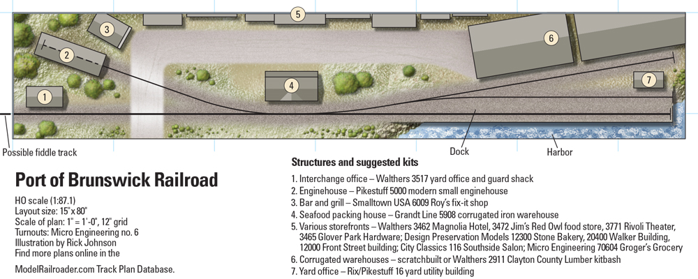
This track plan is actually a Layout Design Element (LDE), adapted from some industrial sidings on the Central Connecticut RR. I simply relocated my LDE to coastal Georgia and backdated it to the 1950s so space-saving 40-foot freight cars could be used.
On a very small layout such as this, every inch counts. The wharf track must hold five 40-foot freight cars in the clear. A 3-foot length of flextrack is ideal for this. The two other yard spurs each hold three 40-footers, with half a car or so to spare. The yard lead must be long enough to let three cars and a locomotive clear the points on the wharf track switch.
Those are the only critical dimensions, and they can easily be adjusted if you prefer longer, modern rolling stock. As shown, the Port of Brunswick layout is 15 x 80 inches and can be built on traditional open-grid framing or a hollowcore door of appropriate width.
Light, code 70 track looks great and is easy to lay on such a small layout. Keep in mind that using different turnouts than the ones shown in the plan may affect the layout’s dimensions. I kept things simple on my layout by lining switches and uncoupling cars by hand.
I’ve suggested some inexpensive plastic structure kits, but this layout would be a good showcase for detailed craftsman structures and rolling stock. Trees are another important scenic feature, mostly low-growing softwoods with a few live oaks.
Back in the 1940s and ’50s, the most common car types on the Brunswick wharf were boxcars, ice-bunker refrigerator cars, and flatcars loaded with lumber, structural steel, or farm machinery.
Bulk commodities such as oil, coal, and kaolin clay were handled in another part of the port, so tank cars and hoppers wouldn’t appear on this layout.
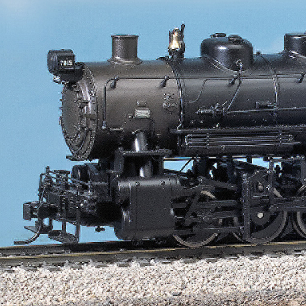
The Port of Brunswick is a one-locomotive railroad. This can be a leased Alco or Electro-Motive Division switcher, or an ancient 0-6-0 spending its last few years shuffling cars around the docks. My motive power is a General Electric 45-ton side-rod diesel, a favorite of Southeastern port authority short lines. And since there’s only one engine, you can make it a real showpiece with extra detailing, eye-catching weathering, and sound. — Paul Boehlert, from “Track plan for a port on a shelf” in the May 2016 Model Railroader
A rail-marine connection in the Pacific Northwest
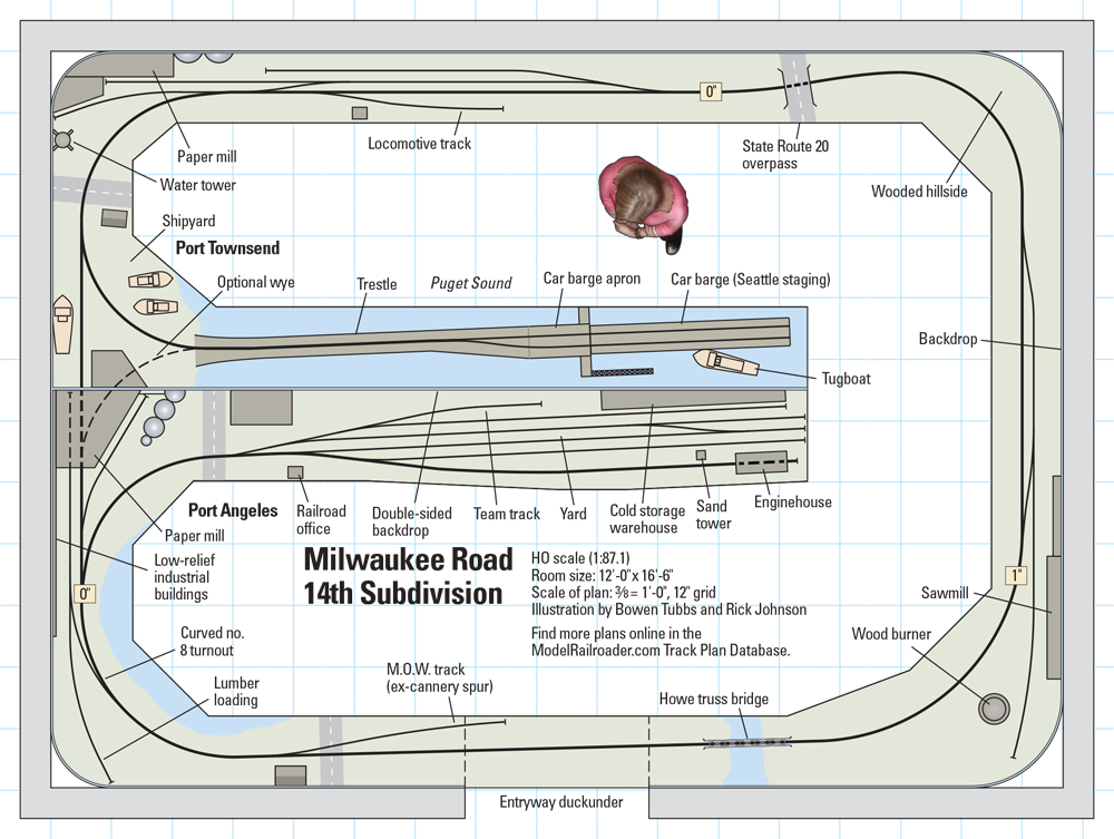
I designed this track plan to conceptually follow the prototype line and its operation, yet have enough switching opportunities to keep two operators busy for a couple hours. Trains run point to point from the yard in Port Angeles to the railroad car barge in Port Townsend and back. The car barge could act as a visible staging yard with different cars swapped out between operating sessions.
Like the prototype, forest products would dominate the layout’s traffic. However I’ve included a team track and a cold storage warehouse in Port Angeles to add some variety.
I also included an optional wye on the plan between Port Townsend and Port Angeles. This additional track would allow continuous running and provide a way to turn trains without having to remove them from the track.
The plan has several prototype-specific scenic features, including large paper mills at each end of the line, an enginehouse in Port Angeles Yard, a “wigwam” wood burner at the on-line sawmill, the Port Townsend shipyard, and the long trestle to the car barge apron at Port Townsend. The scenery between the ends of the line would be primarily thick evergreen forests. — Bowen Tubbs, from “A rail-marine connection in the Pacific Northwest” in the December 2013 Model Railroader
Rail-marine operations on a shelf
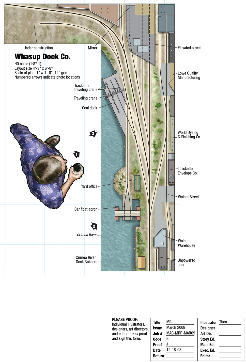
I planned the layout on a piece of plywood, using Atlas Snap-Track sections and turnouts from my previous layout. This mock-up helped me visualize my track plan and check clearances and operation.
I built the benchwork using 1/2″ plywood on a 1 x 4-inch frame. The benchwork sits on a ledger strip mounted along the wall. A single straight leg and L-shaped brackets that I made from 3/4″ plywood support the benchwork.
Except for some temporary flextrack on the unfinished section of the layout, all my trackwork is handlaid code 70 rail on individual wood ties. A friend taught me how to handlay track and build turnouts 20 years ago, and although it’s not my favorite task, I enjoy the finished results.
My biggest challenge was the crossover for the loading track at the coal dock. After two attempts I successfully installed and wired the crossover. I used parts from my first attempt to build a crossover on one of the unpowered tracks for the traveling crane. — Barbara Brunette, from “Rail-marine operations on a shelf” in the March 2009 Model Railroader
A rail-marine showcase
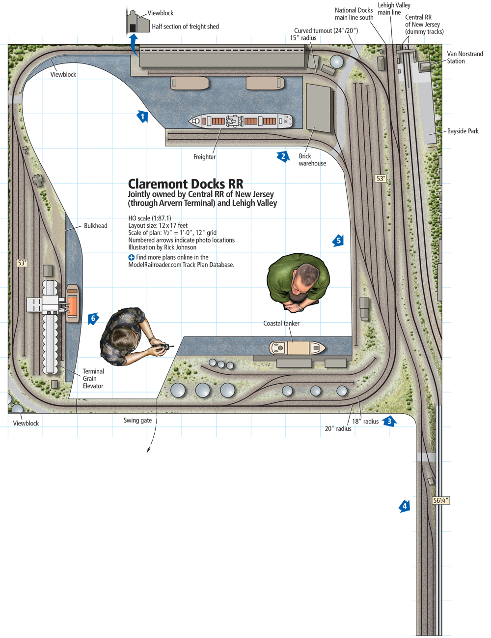
When I started work on the 12 x 17-foot HO scale Claremont Docks RR, I wanted to combine childhood memories with my interest in rail-marine modeling.
The CNJ, which had a large presence and extensive terminal facilities in Jersey City, didn’t lend itself to the small harborside switching layout I wanted to build. After studying a 1942 Army Corps of Engineers map, I selected the Lehigh Valley RR (LV). The LV main line, as well as its National Docks branch, ran parallel and very close to the CNJ at Van Nostrand Place. I recall strings of coal hoppers behind small LV diesels rumbling by on the half-mile-long steel trestle that spanned CNJ’s nearby classification yards.
A spur came off the National Docks branch and went to a small LV harborside terminal popularly referred to as Black Tom. This finger of land jutting into New York Harbor could be modeled with reasonable selective compression. It had what I wanted: A boat basin served by both a multistory brick warehouse and a large corrugated metal freight shed, a terminal grain elevator, and a tank farm. These three signature elements, the Van Nostrand/Bayside Park area, and the steel trestle were the perfect ingredients for a model railroad.
With the structures selected, I turned my attention to the track plan. I wanted continuous running, so I created a loop rather than a more prototypical linear configuration. Information on Black Tom was hard to find, but I did have Army Corps of Engineers and Sanborn Fire Insurance maps. Also, I had prototype photos of three of the five signature elements I wanted to model. I couldn’t plausibly claim I was building the prototype. Rather, I was using the prototype to create a representation that pleased me.
Setting the stage
The benchwork is cantilevered off the wall with L girders, joists, and risers as needed to vary the elevation. There’s little variation in elevation except for the trestle and the bluff above Bayside Park. Ground level is 53″.
The fascia is 1/8″ hardboard, as is the 24″ valance suspended from the ceiling. The valance, featured in the June 2012 issue of Model Railroader, serves to partially conceal the layout lighting as well as to direct the viewer’s eyes to the layout. The viewing window is 19″ high, except in a few areas where I added extensions to discourage wandering eyes. I hung single-tube fluorescent lamps on the ceiling over the layout and used Excella full-spectrum tubes. I spaced the lamps about a foot apart, which was a mistake. The light level is only marginally sufficient. I should have used more lamps. — Howard R. Lloyd, from “A rail-marine showcase” in the July 2017 Model Railroader