


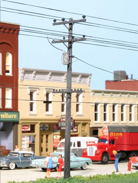
Realistic utility poles with wires bring this model railroad town scene to life.
Get detailed prototype information on utility poles in this previously published article by author Jeff Wilson. You’ll learn how to make your model railroad scenery more realistic by adding utility poles and wires.


great article
Great article!
It may be an older article but I’m looking at it again. The comment from Nick made me look at the “teaser” picture harder. You’re correct that one input on the transformer primary is connected to the neutral but if you look harder you’ll see the other primary input is connected to the middle phase, correctly wired to supply power!
I realize this is about four years after the fact but great article. Every model railroad should employ electric utility lines. Look around. They’re everywhere. This level of detail is what makes a great model railroad great. Being employed in the electric utility industry as an Electrical Engineer, and in particular working on Distribution Construction Standards, I get paid to notice the small things when it comes to utility poles/lines.
The photo currently being used above on this teaser page depicts a 3-Wire Delta Sub-transmission system on the top crossarm with a 4-Wire on the crossarm Distribution primary underbuild(crossarm second from the top). Then another rather unrealistic crossarm below the Distribution crossarm with what appears to be railroad communication lines. I suppose the bottom crossarm could be transformer secondary distribution if a the number of lines was half what is there now. I was surprised to see the level of detail goes right down to the different color of insulators that are used in Distribution. On older systems, brown insulators were used for phase wires(where the power comes from) and white insulators are used for the neutral(where excess power and fault currents go), although in this example it appears the neutral insulator is grey.
In the photo, the primary transformer connection(top of transformer) is seen connected to the neutral of the primary which will not transfer any power to the transformer. The customer has no power in this scenario. The proper transformer connection will be to any one of the phase wires(brown insulators) of the Distribution underbuild.
Couple the information from this article with a close study of the small details seen in prototype installations and you can turn a great model railroad into an excellent model railroad.
Very nice, it's the attention to details like this that can really make a scene come alive.
I really enjoyed this article. It was just what I was looking for to better enhance my layout, and to help me develop my skills a little bit more.
Thank you for this well written, informative article. Appreciate the download opportunity. Roy, Raleigh N C
Some useful ideas there. hanks for sharing that article as a pdf.