


Imagine you’ve just begun running trains on a layout equipped for Digital Command Control (DCC) and suddenly your locomotive and all the other layout action jerks to a halt. Seems like a short-circuit is to blame.
Often times this problem is caused by a derailed car or locomotive traveling across a turnout set against it, which immediately trips the internal circuit breaker of a DCC power booster. In other cases, sound-equipped locomotives with short duration, high current surges (sometimes greater than 10 amps per locomotive) can also be the culprit.
While these things can happen on any layout, their occurrence doesn’t have to shut down the entire railroad. One of the easiest ways to resolve this type of disruption is to install power districts, which divide the power bus and tracks into separate zones.
Defining districts
Power districts can be created using either a circuit breaker (an electrical switch that automatically protects the DCC system in the event of an overload) or a booster (an auxiliary power supply). You can also use a combination of the two to create power districts.
On a small to midsize railroad where only a few locomotives are in operation, circuit breakers allow you to easily subdivide the railroad. Using circuit breakers to establish zones is more economical than purchasing additional boosters and power supplies. There’s no limit to the number of breakers that you can tie to a single booster’s output.
Digital Command Control circuit breakers, including CVP Products ZoneShare, DCC Specialties PowerShield X, and Digitrax Power Management System PM42, are offered by various system suppliers. Breakers are typically available with one to four separate outputs.
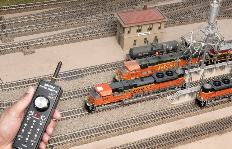
However, keep in mind that circuit breakers share a booster’s output. They do not increase the power available to run locomotives, sound systems, and other devices. Although breakers can help prevent some issues, outages stemming from the high current surge of multiple sound-equipped engines can still halt operations if you don’t have enough current available. A yard or an engine terminal, such as the one shown on Model Railroader’s Milwaukee, Racine & Troy layout on the previous page, is a likely place for this to occur.
There are several approaches to solve this problem. One option is to install on-off toggle switches on staging yard and engine terminal tracks, avoiding the current surge caused by several sound-equipped locomotives starting up at the same time. A second option is to add a booster with sufficient current capacity to the district. A third solution is to install special circuit breakers that are designed to manage the current surge caused by multiple locomotives.
Practical power routing
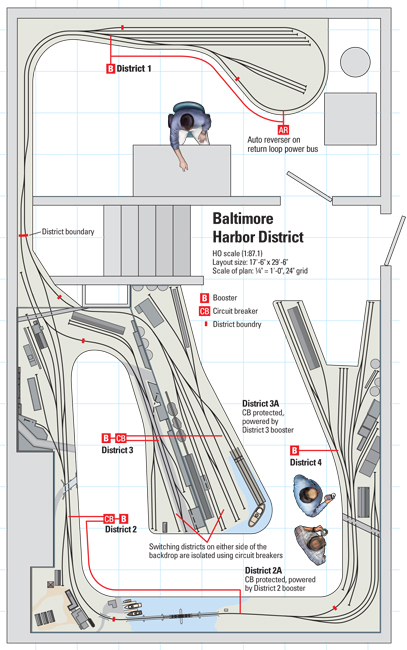
To power my Baltimore Harbor District HO scale layout, shown above, I elected to use a combination of boosters and circuit breakers. At most, five locomotives operate simultaneously on my layout, so a single five- or seven-amp booster would be adequate. I could have simply established zone protection with circuit breakers, one for each of the five switching districts.
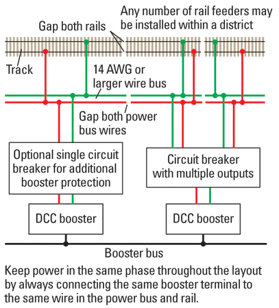
On the other hand, I could have installed a booster for each of the switching districts, along with some circuit breaker protection to subdivide long stretches of track. See fig. 1 (above). Powering an extended length of track isn’t an issue, but it is helpful to keep an individual power district within an operator’s field of vision. In the event a problem arises, the crew will be more likely to locate the cause if they can see it.
For more extensive protection, I could also install an external breaker on the booster’s output. Some experts indicate that this practice provides added protection for the internal breaker, helping avert booster failures caused by repeated short circuits.
As shown in fig. 2, I installed four boosters around my layout to reduce voltage loss caused by running long power bus wires. I also wanted to avoid issues caused by the heat buildup that occurs when boosters are clustered in a central location. I located the boosters at the centers of their districts, rather than at the endpoints. This is particularly important if a layout has few feeders, and instead relies mainly on track power flowing through rail sections, which have a much higher electrical resistance.
Paul has used it for years in his staging yard without shorting problems. Although it wasn’t necessary for Paul to modify or replace these turnouts, it helps to know common sources of electrical short circuits, even on the newest turnouts.
Wiring that works
Many DCC manufacturers recommend that a builder converting a layout from DC to DCC operation also replace existing power wiring with new 14-gauge or larger power buses. All too often, older wiring is inadequate to carry the DCC signal. Existing rail feeder drops can remain intact, as long as they are keep to short, 18- to 20-gauge runs. For layouts built in larger scales, consider using a heavier 10- or 12-gauge power bus and 16- or 18-gauge rail feeders.
I seldom use rail joiners on my layout, so I attach feeders to every length of rail. It’s been my experience that joiners aren’t reliable electrical conductors, even when they’re soldered. Although I had to install scores of feeder drops, I’ve always enjoyed solid, reliable power to the rails.
I’ve also reduced short circuits on my layout by insulating the turnout frogs so that a train running across them will not cause a short. Depending on how tightly the points are sprung, locomotives may even run through a switch lined in the other direction. Since all-wheel pickup is common on contemporary locomotive models, I use a non-powered frog to eliminate unintentional shorts without introducing other electrical issues.
Altering a turnout in this manner isn’t hard, as many of today’s commercial turnouts can be used with powered or non-powered frogs.
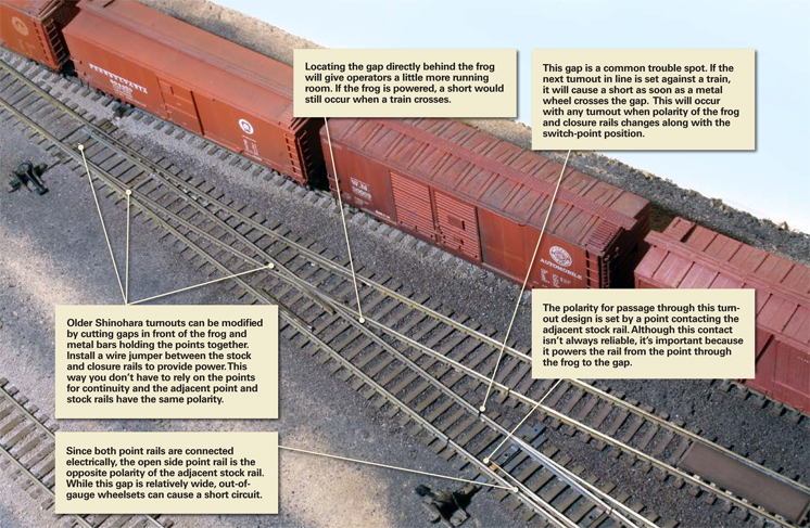
My layout also has a staging yard that includes supposedly “DCC-unfriendly” turnouts. As shown in fig. 3, the open point on these older turnouts is opposite that of the stock rail, which makes it possible for an out-of-gauge metal wheelset to cause a short. Since I seldom experience electrical issues with these turnouts, I’m not compelled to replace them. Although there may be issues with a particular turnout, most can be used
trouble-free if the wheelsets on your rolling stock is properly in gauge.
Proven practices
Although some these suggestions may seem like overkill for operating one or two trains, you’ll gladly welcome reliable performance when you’re hosting an operating session with several trains running simultaneously. That’s precisely when you won’t want weaknesses in your model railroad to show.
The power requirements for a given layout depend on a combination of factors. There’s the power output of the DCC system, wire gauge and length of the feeder bus or bus sections, gauge and length of the feeder drops from the rails, track length between feeders, poor solder joints, number of active locomotives, decoder current requirements, and the power consumption of motors. Every model railroad is unique. The recommended specifications for these items are normally listed in the DCC system installation instructions and in DCC handbooks, including DCC Projects and Applications, Vol. 1 (Kalmbach Books).
Following the recommendations will provide adequate capacity, but if problems occur, review your layout’s overall power requirements and your DCC system’s capacity.
Power distribution
- Use 14-gauge or larger wire for power bus from booster output. Rewire the layout when converting from conventional DC to DCC.
- Subdivide the power bus when using circuit breakers, discrete boosters, or a combination of both to create independent zones, isolating the effects of short circuits.
- Locate boosters at the centers of power districts to reduce the average distance of the DCC signal transmission over each zone’s power bus.
- Install dedicated high-current boosters or “intelligent” circuit breakers in areas with high activity, especially where several sound-equipped locomotives are in operation.
- Where possible create power districts that are within an operator’s field of vision so they can easily spot problems and correct them.


Paul, I enjoyed this article, especially since it is timely for me. I hope you’re still fielding questions (4 years after writing the article!). My layout has 6 districts, each with a booster. Two of the districts are further divided into 2 or 3 power districts by DCC Specialities circuit breakers (or reversers). My question relates to the details about the best way to make the connections between the boosters and the circuit breakers.I saw a video recently where the modeler daisy-chained the circuit breakers from the booster output (and then took the bus power off each of the circuit breakers). Is that a good way to do it? An alternative would be to run the booster output to a terminal strip and then connect the circuit breakers to the terminal strip.
Thanks.
How do you run bus wires for parallel tracks/ Diverging tracks? Service tracks into a roundhouse and adjoining multi track yard?
Good article Paul.
Do you use different bus wire colours for your districts?
I find this assist wiring and debugging especially where districts may overlap such as a return loop, or different level tracks that are different districts, but the bus underneath is close by.
Good ideas but for a novice or beginner looking at this it seems abit daunting. The prospect of soldering rails and adding power districts, it almost seems similar to the old dc layouts with blocks.
Good article with practical tips. I agree with Paul about the older Shinohara turnouts. I have not had a problem with DCC as long as there are isolation gaps ahead of the turnout frog and the turnouts are electrically fed from behind the switch points. Even my dual gauge and HOn3 Shinohara turnouts work well with DCC.