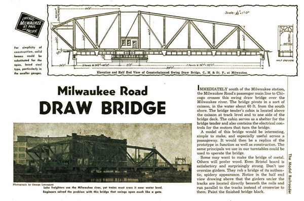
In the January 2012 Model Railroader, Jim Richards explains how he kitbashed a Walthers double-track swing bridge into an offset swing bridge.
The prototype Milwaukee Road bridge Jim modeled first appeared in the July 1947 MR.
Introducing the all-new Trains.com Forum! Become a part of our Community! >>VISIT NOW
| Last updated on January 12, 2021


An online extra from the January 2012 Model Railroader
In the January 2012 Model Railroader, Jim Richards explains how he kitbashed a Walthers double-track swing bridge into an offset swing bridge.
The prototype Milwaukee Road bridge Jim modeled first appeared in the July 1947 MR.

Members enjoy 15% off any purchase in our store. Join Today!

Model Railroader 2025 Calendar
Be inspired all year long with Model Railroader’s all-new 2025 calendar!


nice project for my future layout
There is another very similar, the counterweight is a bit different, old Milwaukee Road swing bridge crossing the Mississippi River in Saint Paul, MN. It is still in use.
In one of the mrr'ing bridge and trestle reference books (don't recall which now though) there is this same bridge but it was referenced as being here in Yuma, AZ. From my research, knew it had been mis-labled with one next to it but we werent sure about where the other was for sure. This helps clear that up! Now to rememebr which book it was so I can put a note on it……
Another great article and ideas!
For Steven Otte:
By drawing style and caption typeface, I think it is a fair bet that the illustration is from a Railway Track & Structures Cyclopedia published by Simmons-Boardman.
Cant wait for January issue .Have one of these kits and it will definatly get the treatment.
You can call or write the Coast Guard Bridge office for your local area for more information on bridges over navigable waterways. Most of the records I have here at work date back to 1899. If the drawings are 8.5 x 14 or smaller I can scan them without much trouble. The full size drawings I have to take them to engineering and request scans and takes more time not to mention I do have regular duties to attend to. Not all the records are complete as they are 113 years old or the iron ink is fading. I cover the Great Lakes and tributaries here. If you make a request refer to the U.S. Coast Pilot, each bridge is listed by waterway and has a mile marker assigned to it. The Coast Pilot is available online. When making requests never ask for the whole file, just ask for what you want. Some files may be 500+ pages not counting drawings.
I think it is great to have the drawing and would really like to see a lot more resources like that as well. I have noticed there had been a lot more resources like that in older MRR mags then I've seen in the past few years.
Keep up the good work and Happy Holidays to all.
Dave
Though I'm not an engineer,I do know alittle about load and cant functionality.It appears to me that the cassion is off set for a more usable waterway.The river is narrow here so to put the cassion in the middle would have reduced the channel of water traffic.As far as counter weights it seems a no-brainer that there has to be a count er weight or the long side would sag and bind the mechanism.the load that it is transferring is three times greater to the cant. side.
The original bridge was built in 1872 and re-built in 1903. Around 1925 the oil lamps marking the navigation lights were converted to electric. New pier protection was installed in 1948 and 1952. Believe it or not; several railroad bridges in this area were built by the Baltimore and Ohio Railroad, they never owned the bridges or operated over them, they just built them. I cannot find the builders sheet for this particular bridge in my file, it may be in book form at the other end of the cabinet…
There were 2 of these swing bridges just a few miles from the house that were in service till the early 80's I believe. 1 was tore down, the other was taken apart and put back together a couple 100 yards from where it sat, and is being used as a musuem piece.
I believe bridge dates to 1904. Our Structures Crew replaced the counterweight for Menomonee (this bridge) in June 2011 for Canadian Pacific. In 2007, I was bridge tender for Menomonee. I have many detail photos and am in process of completing the same model kitbash.
It's very architectural in form and simplicity and that's coming from a Registered Architect. Don't forget that there is no live load on the bridge when it was in the "open position” Therefore the stress on the cantilever was reduced to the structure (dead load) itself when open. There are two moment stresses at work here one being the short cantilever exerting a force down to counteract the longer arm, the other being the connection of the structural bridge deck to the caisson which resists the overturning probably with high strength bolts. I’m not an expert but I would guess that as with most moving structures additional weights were there to facilitate the balancing so that the swing mechanism would operate smoothly. The offset is in response to the need for the widest opening achievable. That’s my old O.S.U. Architectural School training kickin’ in
James from Ohio:
It's likely this drawing was reproduced directly from Milwaukee Road blueprints, rather than being redrawn in-house. Since it was published in 1947, it's understandably a little hard to say what they were thinking.
As for the weight to make the counterweight, that depends on what the materials you're using weigh. I'd suggest making your counterweight hollow, and adding lead weights to balance it after the rest of the construction is complete.
Already submitted one comment. So, now that I enlarged the drawing I see that the short side overhang carries a counter weight. Any suggestions for figuring our how much the counterweight should weigh if building a model working bridge compared to the weight of the actual structure?
Why is the drawing scaled with an architec's rule and not an engineering rule? Bridges are engineering designs and not architectural works and I would think drawings should be scaled accordingly. My old engineering training is showing through. Also, could someone explain the purpose of the shortside overhanging portion of the structure. What load is it transfering?
Whenever I check in I find something new!
Never seen one like that before – good ol' USA engineering 🙂
Great drawings. Not necessarily something that I would use, but fun to look at. It would be great if MR started doing these more often.