Why would anyone model the Stockton & Copperopolis, an obscure short line with a name that sounds made up? Or model this little-known prototype in the 1890s? Most importantly, would it be practical to build it as a large, prototypically faithful model railroad capable of realistic operation and equip it with authentic locomotives and rolling stock?
I’d previously built a couple of small layouts set in the 1890s, the largest of being my freelanced Moraga Springs Northern Ry. (MSN) in an 11 x 12-foot spare room [see Model Railroad Planning 1995 – Ed.]. But there was no guarantee that a large, reliable, multi-operator railroad depicting that early an era was practical.
My first thought was to build a larger MSN, but modeling a prototype sounded even better. Years earlier, on a whim, I’d started researching the S&C. The more I read, the more interesting the railroad became to me.
A brief history
The owners of the Southern Pacific rapidly acquired the S&C, but they left it to operate under its own name until it became an SP branch line in 1889.
With the copper mines dormant, the S&C settled into a routine of hauling wheat from the farms along its route to the river steamers and flour mills in Stockton, and supplies to the gold mining region. Both Milton and Oakdale became busy freight forwarding centers serving the mining towns of Sonora, Jamestown, Angels Camp, and others.
By the 1890s, wheat traffic was still important, but the large farms were being broken up for cattle ranches, produce farms, and citrus orchards. California had been providing the nation with fresh fruits and vegetables for several years, and the debut of iced refrigerator cars accelerated this trade.
Modeling the S&C
But several questions had to be answered before I felt comfortable tackling this sizable project:
• What would I use for locomotives and rolling stock?
• Could era-appropriate locomotives pull trains of reasonable length?
• Could I find information on track arrangements and industries for the various towns?
• Were there enough photos or drawings of the railroad’s structures for me to build accurate models of them?
• What year would I pick?
Locomotives and rolling stock
Most of the locomotives on the S&C were 4-4-0s, but no commercial models were really suitable. I could rework an older brass import to model one engine, but the rest would have to be scratchbuilt. Fortunately, several locomotives from my MSN Ry. could serve as standins until that could be accomplished.
I’ve found that small, light locomotives need electrical wipers on all driving and tender wheels to provide reliable
pickup. I’d been using DCC and found it practical to add sound decoders and speakers in most of the larger engines. Based on the success of these modifications, I felt the motive power problem was manageable.
The downside of smaller engines is that they weigh less, which translates into reduced pulling power and short ttrains. My hopes were that one of my Americans would be able to pull 10 cars and a caboose up a 1 percent grade.
Freight cars of this time were mostly 28 to 34 feet long. I already had 50 to 60 freight cars and several passenger cars, but estimated I’d need at least 200 to support my desired traffic level. A few manufacturers make 19th-century cars, but my stockpile of kits still needing assembly would be enough to at least get a start on the roster.
Track, industries, structures
I found an original station plat book of the S&C from 1874 to the late 1880s. It showed the length of every siding and dimensions of all railroad structures as well as many industries served by the railroad. Dates of their construction were often included. The California State Archives in Sacramento also had track diagrams from a 1912 valuation study. The National Archives in College Park, Md., have the field notes of the 1916 ICC valuation study, which yielded more structure information.
As I visited various libraries, museums, and historical societies, I found more photos of the railroad than I ever expected. Gaps in information remain, however. This is one of the challenges of modeling a time when cameras were still luxuries for most people. Nevertheless, I found more than enough data to re-create the flavor of the railroad.
Layout design criteria
I needed plenty of distance between towns to give train crews the feeling of actually going somewhere. Including a number of switching locations was also important. At least two train lengths, or about 14 feet, seemed to be a good minimum distance between sidings.
My last railroad was built with code 70 track, which looked large to me when compared to the smaller engines and cars. It scales out to about 105 pounds per yard, much larger than the 60-pound rail of the prototype. I didn’t want to handlay track, so I compromised and used code 55, which scales out to 70 pounds per foot – close enough.
Using code 55 rail meant that I would have to build my own turnouts. This initially discouraged me, but a trial using Fast Tracks turnout jigs showed that I could make a good turnout in a reasonable amount of time.
Operating potential
Many prototype roads that intrigue me as modeling candidates probably wouldn’t be very interesting to operate. Would the Stockton & Copperopolis fall into that category? More research into rail traffic typical of California in the 1890s reinforced my thought that this era held the potential for several modelable industries along the railroad. Although wheat was the major cargo, fruit, cattle, produce, coal, and manufactured goods would make for varied and interesting operation.
I chose to model 1895 for two reasons. First, in 1892 the railroad opened up its extension to Merced, which would generate more traffic. Second, I wanted to model a year prior to 1897, when the Sierra RR was built into the heart of gold-rush country, reducing the importance of Oakdale and Milton on the S&C. So I split the difference.
One problem faced by budding prototype modelers is that no prototype seems to have all of the features we would like in a model railroad. The Stockton & Copperopolis was no exception. For example, I wanted to run full length Pullmans and 2-6-0, 4-6-0, and 2-8-0 locomotives, but the S&C didn’t have those. I also had a sentimental attachment to my fictional MSN. However, if the MSN was granted trackage rights over part of the S&C, I could use it to do all the things that the S&C didn’t do, and generate more interchange traffic at the same time.
With my concerns over practicality resolved, I pushed ahead with planning the layout. Analyzing the area available to me suggested that I could model the line from the port of Stockton to Oakdale and include the branch line to Milton as well. Staging tracks would represent connections south to Merced and north to the MSN Ry. The best part is that this could all be done on a single level; building a double-deck layout would probably result in more railroad than I could manage.
A single level would also allow me to have the benchwork at what I considered an ideal height. My last railroad had the track at 56″, which was great for viewing but a little high when uncoupling cars. Since operation was a major goal, and several scenes would be fairly deep (up to 30″), I decided to lower the base height to 48″.
The biggest design problem was how to include the important junction and wye at Peters. When a line branches off the main, there has to be a way for operators to cross from one side to the other. That often requires a duckunder or movable bridge. [See “Railroad crossing solutions” by Paul Dolkos in MRP 2000. – Ed.]
With the track height at 48″, a duckunder would be wearing on operators, and lift-out sections can have alignment problems, usually because of humidity. I must have gone through 10 plan iterations as I tried to work around these inconveniences. No luck. Finally, I gave in to the fact that including both branches would require a swinging gate, which I described in the MR special issue How to Build More Layout in Less Space, published in August 2010.
As I worked my way through the design process, my research proved invaluable. I based track arrangements at each station on the S&C’s station plats. It was important to me to include many of the scenic and operational features that initially attracted me to the Stockton & Copperopolis.
Along the right-of-way
The river port of Stockton provides the S&C’s key connection with the rest of the world. Grain warehouses and flour mills lined the wharf, and many other industries – iron foundries, tanneries, paper mills, farm implement manufacturers, even windmill makers – called Stockton home. The centerpiece of the S&C terminal at Stockton is the three-track covered depot right on the wharf.
As was typical in those days, wheat moved in sacks rather than in bulk from grain elevators. There were many grain stroage houses and newer fruit-packing plants along the railroad. Since I wanted the railroad to reflect the agricultural base of the region, one modeling must would be a wheat-harvesting scene.
Towns like Farmington and Oakdale were basically agricultural, but had other industries as well, reflecting changes occurring in the 1890s. At Farmington, a grain warehouse, a produce packinghouse, and a coal dealer were all served by the same spur. Although this seems more like a model railroad artifice, it was typical of the time.
Most of the commerce of the southern gold-mining region once passed through the little town of Milton, the eastern terminal of the S&C. I discovered, however, that I had enough space to include the projected but never-built line over Gopher Ridge to Copperopolis. In fact, the railroad actually looked into such an extension to tap an 1890s revival in the copper mines, so I decided to correct the prototype’s oversight by extending the line to Copperopolis on my model railroad.
Holden was little more than a small siding serving a farm area. In the 1870s, it was envisioned as a junction point with the narrow gauge Stockton & Ione RR, which would have served the lumber and coal industries in Amador County. Although the prototype Stockton & Ione built only three miles of track before running out of money, photos survive of the handful of boxcars and two Mason Bogie locomotives that were built for the railroad. My affection for the Bogies and the fact that the S&I was three-foot gauge convinced me to add this slim gauge feeder to my S&C.
Scenery
The San Joaquin Valley is pretty flat for the first 25 or so miles east of Stockton. After that, low rolling hills appear, with the Sierra foothills abruptly rising from the valley floor.
In the 1890s, the flatlands were occupied by wheat farms. The hills, covered with California’s golden grass but bare of trees or even bushes, became the province of the cattle rancher. The temperature in the summer is frequently over 100 degrees for days at a time. Although the grass is green during the spring, in summer it rapidly turns dark brown and finally gold. In the Sierra foothills, the temperature is somewhat lower, and evergreen bushes and oak trees are abundant.
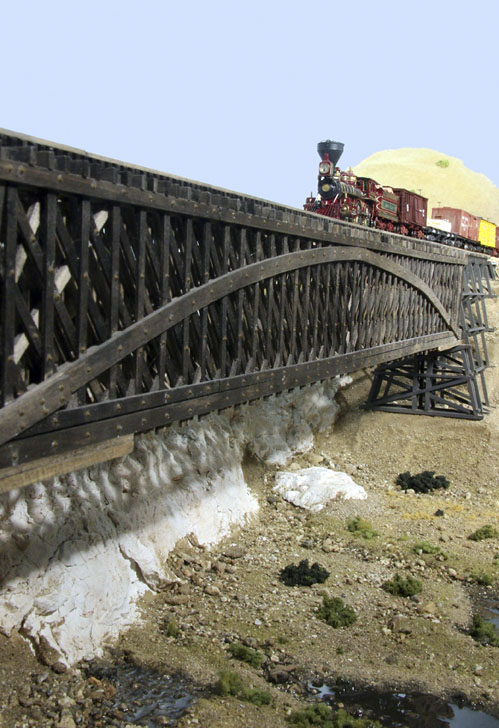
The major scenic feature on the line is the bridge over the Stanislaus River just north of Oakdale. The prototype was made of two wood Howe-truss deck bridges with trestle approaches for a total of 800 feet in length. I have room to duplicate this bridge in its full scale length; it’ll be an eye-catching model.
Progress report
Construction on the model railroad started in September 2007 at Stockton, with the track reaching Oakdale a little over a year later. I held the first operating session in June 2009. Since then, I have hosted eight or nine local operators at monthly sessions.
Trains run by timetable and train order. The timetable lists both first- and second-class trains, and several extras
are also called. The dispatcher’s desk is located in the adjacent crew lounge, and an operator copies train orders and acts as an agent for the entire railroad. Telephones and fast clocks are located throughout the railroad for the convenience of the crews. [See “Add work stations to your layout” in the June 2010 Model Railroader. – Ed.]
Does it work?
All in all, I am very pleased with the railroad. My biggest concerns about equipment and trackwork functioning
reliably have been alleviated. The operating scheme for the railroad works well, and everyone seems to enjoy the operating sessions.
As I look back on the design process, I find that my desire to model a prototype railroad drove many of the decisions I had to make. The era dictated that I would be doing a lot of locomotive and car building. Although there are many structures on the market suitable for the 1890s, fidelity to my specific prototype demands scratchbuilding most of them. Both activities require a lot of time, as did the research made necessary by the lack of published information. But it’s been time well spent, with
commensurate rewards.
Those who model an early period don’t often have the luxury of beautiful ready-to-run cars and factory-painted,
sound-equipped engines. I’m not complaining, just making an observation. It’s a question of what’s important to you.
I doubt that I’d be happy with a modern railroad, so for me, the extra work isn’t really work at all, but instead a source of more model railroading fun. It’s not for everyone, but it suits me, and that’s the important thing. The Stockton & Copperopolis should therefore be a model railroad that will prove to be rewarding long into my retirement years.
Name: Stockton & Copperopolis RR
Layout designer: Don Ball
Scale: HO (1:87)
Size: 37′-0″ x 40′-3″
Prototype: Stockton & Copperopolis RR
Locale: California
Era: 1895
Style: linear walkaround
Mainline run: 240 feet
Branchline run: 100 feet
Minimum radius: 30″
Minimum turnout: no. 6
Maximum grade: 2 percent
Train length: 7 feet
Benchwork: open-grid
Height: 48″ to 56″
Roadbed: foam tape
Track: Micro Engineering code 55 flextrack with handlaid turnouts
Scenery: plaster gauze over cardboard forms
Backdrop: tempered hardboard
Control: Digitrax Digital Command Control
Looking at Google maps, you can still make out some of the railroad grade between Peters and Milton.
Dropped pin
https://goo.gl/maps/rsPP2bCJ7gQyrURu9
Small world, I plan to start modelling in N scale the Pacific Coast Railway, but in standard gauge, this year. I too live in the KC area (Go Chiefs!). Very interesting the challenges of modelling late 1800’s/early 1900’s as I plan to do.
This is not really about the article, but I’ve been looking at track plans for years and have bought and tested many software packages that illustrate various plans, but “what software is this plan done in?” Or is it hand drawn?