


Sometimes in model railroading you need to be a sleuth. Everything on the railroad happens for a reason, and sometimes the reason is you. Following is a case in point:
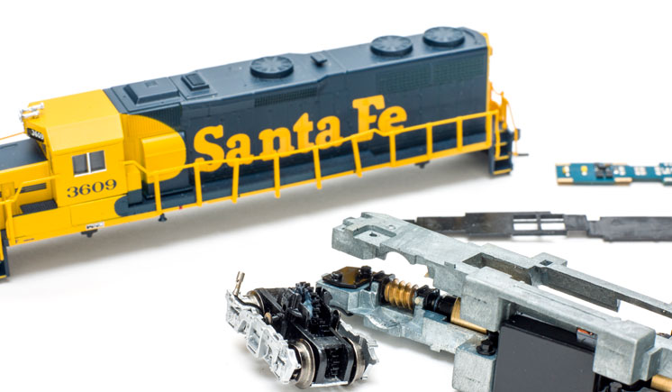
Recently I took delivery of two new Atlas GP39-2s. (Eric White reviewed these for the July 2019 Model Railroader.)
Meanwhile, I’ve been on a campaign to speed-match all of my locomotives. I’m setting them up to run 60 scale mph at full throttle (28 speed steps) and 30 scale mph at 14. My friend Stuart Baker got me started on this. It’s a fine thing when a bright, young software engineer helps you with such matters.
Getting on with the GP39-2s. To jump ahead in my story, I placed the first engine on the track and set my speed limits easily, using an Accutrack II speedometer and programming on the main. (I realize that for quite a few of you, I’m talking gobbledygook, but I’d bet that some day you’ll be setting speeds, too.)
The second locomotive was an entirely different matter. I was able to set the configuration variables (CVs) fine and get the speeds I wanted, but as I test-ran the locomotive, the engine would occasionally go berserk and take off like a rocket. That’s the short way to the floor if you’re running a model railroad. The only thing I could think of was that I had a faulty decoder.
“Hmm,” I thought, “that just might be the problem,” and I wasn’t just stabbing in the dark. I had reason to suspect so, and I’ll get to that.
It took about 15 minutes to connect the feeder wires to the bus wires, another good reason why I should’ve done it a decade earlier. Voila! GP39-2 number two ran just great and had no problem keeping its wits about it.
Eric noted in his review that the current from the wheels was conducted to the frame by wires. I was less than enthused about that. It struck me as a step backward. In the bad old days of the 1970s and ’80s, this was often the case with inferior N scale locomotives and was, along with plastic frames and cheap, three-pole motors, among the reasons they were inferior.
Anyhow, while pulling the shell off the frame, I had dropped the mechanism on the floor and one truck had popped out, with one wire now loose. Because the insulation on the wire was so stretchy, I had a devil of a time getting the end of the wire stripped. Space was tight, but I got the wire soldered back on.
Back to the mystery solved: I used test leads from the track to make sure both trucks were picking up power. They were, but I suspect that my solder joint was just bad enough that the pickup wasn’t quite good enough.
The moral of the story? Well, I can think of two: Don’t drop stuff on the floor, and connect up those feeder wires.


I think the technical term we used to use for part of this was “Fat Fingered”. However your description of the dangling wire reminded me of another technical (non-model railroad) issue I used to encounter in my work. Basically a non-terminated wire is an antenna which can induce all kinds of erratic signals. Would these will impact a DCC controlled layout, I don’t really know since I still run DC only. What I do know is in other technical areas those dangling antenna can cause seemingly random problems.
-Mike in NC,
We have ALL had the “enemy is us” problem on at least one occasion. Thank God our trains are forgiving…
What the author describes here can be a real problem. I ran into it at least 2-3 times when DCC throttles came into being. Some of my railroad friends never had such problems. Keep this article in mind if you should ever see this happening on your layout.