


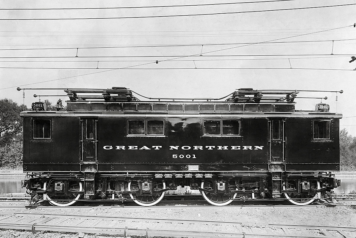
A A three-phase system was used to provide the electrical power to Great Northern units. A portion of the locomotives had two trolley poles to engage overhead wires while the running rail carried the third phase. In the booklet, “New Cascade Tunnel” published by the Great Northern for the opening of the tunnel in the 1920s, the railroad wrote: “An unusual feature of the Great Northern’s electrification is the combination of the alternating-current and direct-current systems. Alternating current is used for transmission from the source of power to the locomotives and direct current is used in the traction motors. The locomotives themselves carry the transformers and motor-generator sets, which change the high-tension alternating current to low-tension
direct current.” — Seth Bramson, historian and author


Thanks Jimmy for your explanation on how the third rail works. As a electrical contractor I understand 3 phase and I know that the grounded “B: phase still exists in this area. It was widely used in industrial applications where a failure of one leg would not immediately shut down an operation but should set off alarms so an orderly shutdown could occur. Most times these alarms were not used or were ignored until a major burndown occurred. Grounded “B” is not understood by many electrical people but is very dangerous in the hands of the ignorant. If you open the connection on the third rail it will immediately will carry the same voltage as the overhead.
Two railways or railroads in Switzerland still use the three-phase system with 2 overhead wires and the rail as the third. They are the Gornergrat Bahn from Zermatt to Gornergrat and the Jungfraubahn from Kleine Scheidegg to Jungfraujoch, the highest station in Europe. The Gornergrat Bahn uses 725V AC and the Jungfraubahn 1125V AC. Both railways are rack or cog mountain railways, the former using Abt rack and the latter Riggenbach.
The locomotives or power cars have 2 sets of 2 pantographs placed at each end of the vehicle as at turnouts or points the wires above have to have large insulated gaps to keep the 2 sets of wires apart and this is why they need 2 sets of 2 pantographs far apart as they cross over one set is in contact with both the wires while the other set may not be.
The Great Northern Railway locomotive may get away with only two trolley poles in contact at any one time and would coast through some of the insulated sections at turnouts or points, although trolley poles mean that the insulated sections could be much smaller.
Italy also had quite a lot of three-phase AC systems on conventional railways until they were replaced by DC overhead systems back in the ~1960-1970’s which were rather simpler and easier to maintain.
If you could measure the voltages– Rail to one wire- 10,000 volts. Rail to other wire- 10,000 volt. Wire to wire- 10,000 volts. I used 10,000 volts as an example; I do not know the actual voltages.
this same circuitry is used today through out the us. Its called open delta config. The two insulated overhead lines provide two of the phases and the third phase is derived by the grounded rails. This will only work when used from a seperate transformer allowing the floating Delta system to have the third leg grounded and carry i/3 of the current. All rail jouners would be bonded so that the return current would come back to the transformer that would have the “middle” leg grounded and bonded.
The engine would have a step down transformer to drop the voltage down to a lower voltage like 600 volts as used in the engines today and this power would drive an electric motor / dc generator to provide power to the motors on the axles.
George, they used 2 trolley poles because there were 2 overhead wires parallel with each other. Those 2 wires along with the rail were the 3 different feeds.
OK, this doesn’t really explain how the system work. Two trolley poles on a single wire is still just two feeds from a single phase circuit. Three phase power is composed of three separate sine waves, one each on three different wires. Running rail carrying the third phase, wouldn’t that be a direct short to ground, or did they heavily insulate the rail from ground? If they did insulate, how did they do it, what fasteners did they use?