When it comes down to it, nickel-silver rail is a pretty poor conductor of electricity. And about the only thing on a layout that conducts electricity worse than nickel-silver rail is a rail joiner. Unless you have a very small layout, never expect one set of track feeders to adequately carry the power and DCC signal to all parts of your railroad. Not only will this arrangement give you poor performance, but it could be dangerous as well.
A DCC booster is capable of supplying much more current to your layout than a traditional DC power pack. But if you have a high-resistance path to your rails (a result of poor or inadequate wiring), a short circuit far away from your booster might not trip the system’s circuit breaker. (For more on circuit breakers, see the September 2007 DCC Corner.) Heat from such a short can damage your wiring, track, or locomotives. It could even start a fire.
A short like this occurred several years ago on Model Railroader‘s club layout, the Milwaukee, Racine & Troy, while the staff was converting it to DCC power districts. The short was on a part of the layout that had not been rewired yet, and it melted the plastic ties of a turnout.
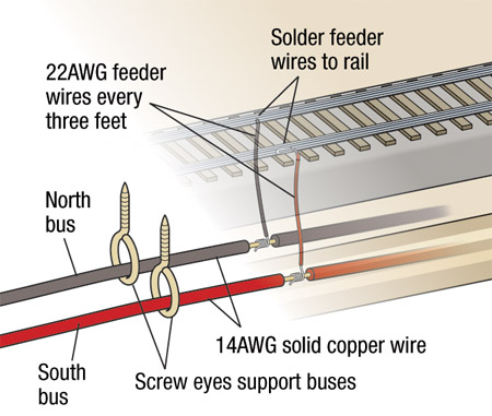
Wire size. To avoid an excessive amount of voltage drop between your DCC booster and your locomotives, your track bus must use wire large enough for the load. The actual minimum wire gauge you need depends on the capacity of your booster and the length of your wiring run. The standard rule of thumb is that for most midsize or smaller HO layouts, 14AWG (American Wire Gauge) bus wires are fine. For O scale or larger layouts, you should use 12AWG wire. Smaller boosters (3.5A) on layouts with short wiring runs can use 16AWG.
Track feeders, the wire that runs from the bus to the rail, can be a much smaller gauge. I use 22AWG feeders on my layout. If your layout calls for a feeder longer than 12″, you’ll want to splice a section of heavier gauge wire, such as 16 or 18AWG, between the feeder and your track bus.
Keeping a logbook with diagrams and notes about your layout wiring is another good idea. This will help you decipher your own wiring practices when looking for electrical problems.
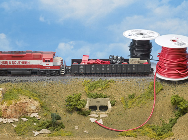
One of the best practices is to use color codes, which creates self-documenting wiring. On my layout, I use black and red wires for track power buses and feeders. If you have places where track buses from multiple power districts are in close proximity, you might consider using different colors for each bus to keep them straight.
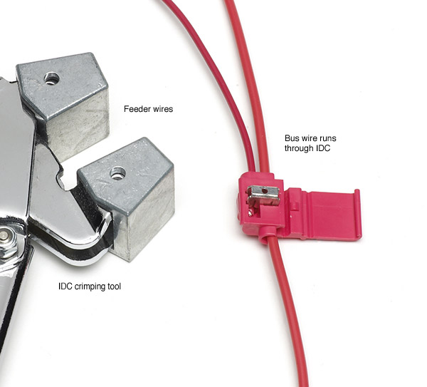
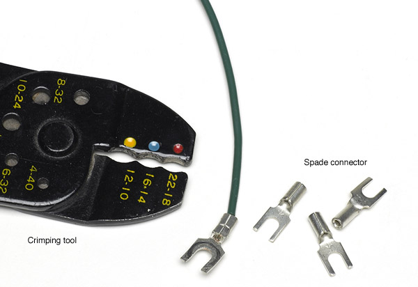
The bottom line is that in either case you must make the connection correctly to assure its reliability, and this requires proper tools. For soldering, you’ll want a good-quality soldering iron with a clean tip, the proper solder (60-40 rosin core, .031″ diameter or smaller), and perhaps some liquid rosin flux. For IDCs you’ll need a special tool designed to close the connectors, as shown in fig. 3. However, while a slip-jaw pliers is not recommended, MR executive editor Andy Sperandeo gets good results using a pair of Robo-Grip cam-action pliers to close the connectors.
Testing your work. Safety is an important issue when it comes to wiring your layout, so be sure to test your work. Once you’ve connected your feeders and track bus to your DCC system, use a quarter to short circuit the track at a number of locations. Make sure the circuit breaker trips, especially when you test the far ends of the track bus. If the breaker doesn’t trip when you short the track, it means that your track bus still has too much resistance. To fix this, you can either try adding extra feeders or doubling the existing bus with a parallel wiring run.
Also, if you’ve split your layout into several power districts, you’ll need to make sure the power supplies on either side of the district gaps are in phase. To test this, use
an AC voltmeter and measure across a gap in the same rail. The voltage reading should be near zero. If instead you get a reading of roughly 14V, your districts are not in phase. In this case you’ll need to switch the bus wire connections for the section out of phase where they connect to the booster.
Lastly, Pricom (www.pricom.com) makes a DCC pocket tester that checks a whole host of parameters about your DCC system, such as the number of bad bits and packets received, track voltage, bit timing, and other information. Simply turn on your DCC system and clip the tester to any section of track on the layout. It will give you an indication of how clear your DCC signal is at that point on your railroad.
It doesn’t take much extra effort to wire a layout properly. The time you spend to do the job carefully will pay off in a layout you can operate with confidence