Videos & Photos Videos Beginners The Salt Lake Route, Part 3: Laying realistic sectional track

The Salt Lake Route, Part 3: Laying realistic sectional track

By Angela Cotey | May 30, 2017

| Last updated on November 3, 2020


Kato's reliable and ingenious sectional track make this 4 x 9 N scale track plan possible

Email Newsletter

Get the newest photos, videos, stories, and more from Trains.com brands. Sign-up for email today!

MRRC0310_601
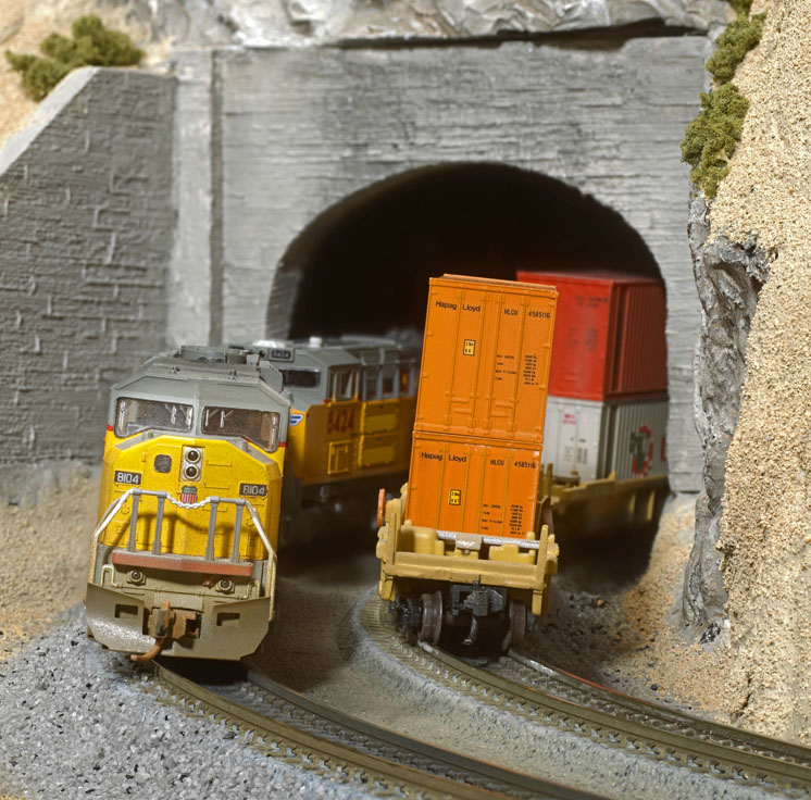
A pair of Union Pacific freights bank into the superelevated curves on the N scale Salt Lake Route. Dick Christianson explains how he installed Kato Unitrack, including the firm’s new double-track sections with superelevated curves (inset), on our project layout.
MRRC0310_626

One of the parameters Model Railroader gave me regarding the N scale project layout was that I needed to use Kato’s new superelevated sectional track (set V11), at least for part of the railroad. What I knew of traditional Kato Unitrack, with its molded roadbed, was positive. The firm’s new superelevated double track looks terrific, with molded gray and black ballast. The crossties are gray, representing concrete. Interestingly, the Union Pacific has concrete ties on the grade through Meadow Valley Wash and Clover Creek Canyon, so the track was prototypical for the area modeled.

I’d experimented with the superelevated track on the Meadow Valley Wash side of the layout before I realized that all wasn’t as simple as it seemed. I first laid out the track so it went directly from a left-hand curve into a right-hand curve. The track clips fit, but there was a heck of a difference in track levels where the sections, which were elevated on opposite rails, met. Clearly, I was missing some sort of transition sections designed to take curves to level and then to superelevation in the opposite direction.

Transition sections

Set V11 included half-sections that transition from a left-hand curve directly into a right-hand curve (or vice versa). At the end of each curve I installed the appropriate half-section to keep the track geometry intact.

The half-section transition was what I needed to bring the curve at the left end toward the center of the layout, instead of parallel to the edge. It functioned the same way at the other end. With the proper placement of straight sections between the curves, the track fit perfectly along the Meadow Valley Wash side of the layout at both ends.

Those half sections came into play on the yard side as well, determining where the molded double-track sections would end and the single-track straights and curves would begin. It was just a matter of which sections to use. I knew it could be done.

Cork roadbed too?

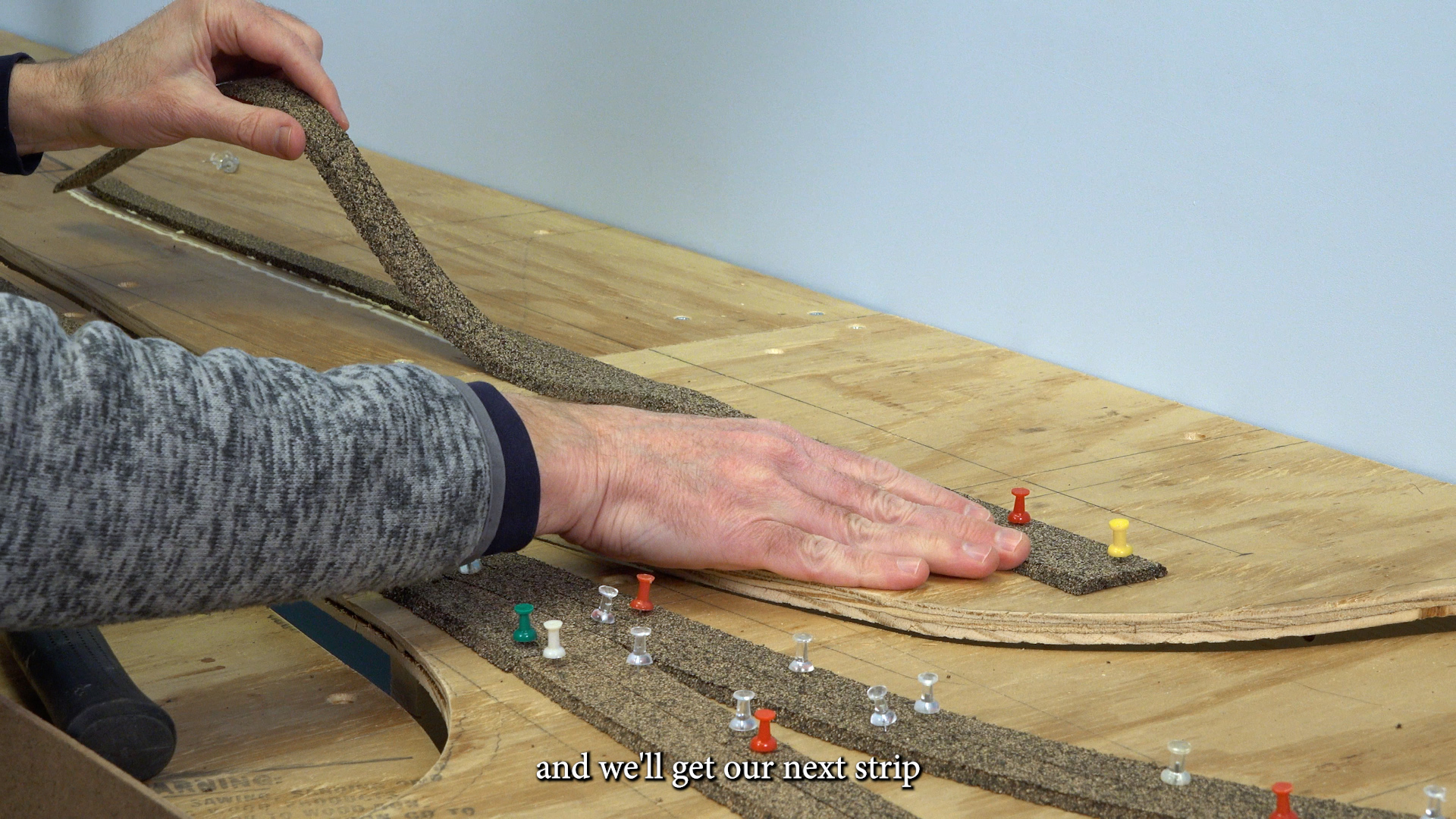
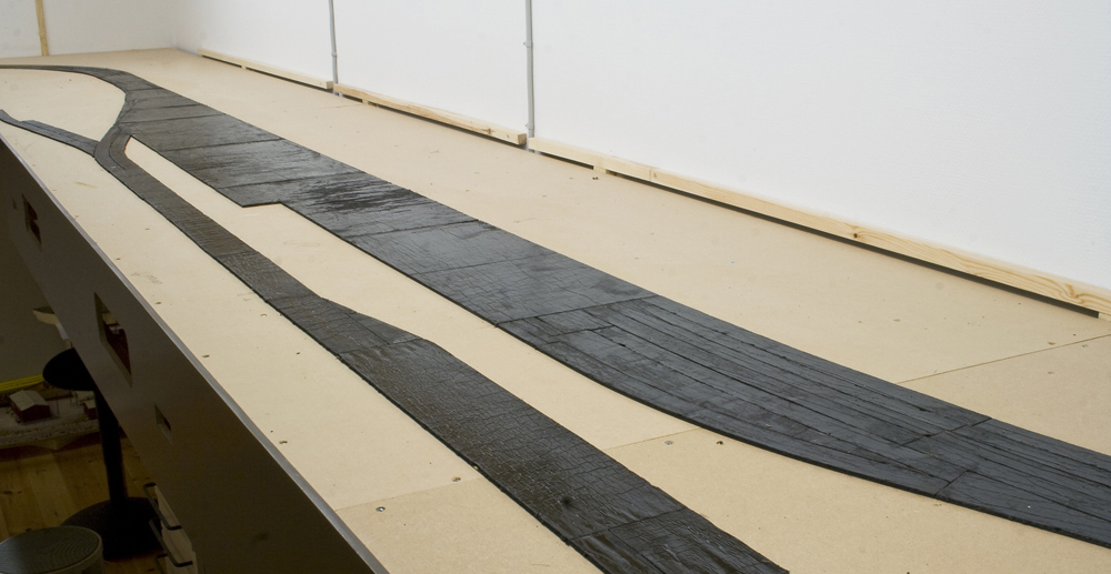
I began by tracing along the edges of the roadbed of the track on the Meadow Valley Wash side. Then I cemented N scale cork roadbed along the outsides so that the beveled edge of the cork aligned with the slope of the molded roadbed. I attached two strips of cork down the middle to provide support and a surface to apply Liquid Nails.

You’re probably asking, “Why would he add cork roadbed?” I felt the cork would absorb some sound. Molded plastic on plywood didn’t seem like a great sound-deadening combination.

MRRC0310_20
Fig. 1 Two types of joiners. There are two ways to attach feeder wires to Kato Unitrack. The first way is with the firm’s short track sections (no. 041) that have small sockets built in for the feeder wire plug (top). The second option is to use track clips/rail joiners (no. 24-818) with the feeder wires attached.
MRRC0310_05
Fig. 2 Wire modifications. Kato turnouts use control wires with a plug at one end. Dick removed these plugs so he could slip the wires through holes drilled in the plywood subroadbed. The turnouts operate manually.
MRRC0310_21
Fig. 3 A solid bond. Dick used five-minute epoxy to cement the miniature plug to the Unitrack. This prevents the plug from falling out when the feeder wires are pulled through the holes he drilled in the layout surface.
MRRC0310_22
Fig. 4 Oh, that’s what it’s for. The blue plastic tool included with Kato Unitrack is for removing the track clip/rail joiner. The tool levers the clip/joiner out of its socket
MRRC0310_03
Fig. 5 Hidden holes. From above, it appears the Kato Unitrack doesn’t have holes for track nails. Underneath the track are hollow tubes that Dick opened with a no. 60 bit.
MRRC0310_04
Fig. 6 Securing the track. To prevent the track from coming loose when moving our portable layout, Dick further secured it to the cork with Liquid Nails for Projects.
MRRC0310_06
Fig. 7 Testing the track plan. Dick laid out the Kato Unitrack on the Caliente yard side of the layout. He positioned the track as far away from the backdrop as possible to make room for the enginehouse and furniture factory.
MRRC0310_07
Fig. 8 Spacing guide. Dick used a notecard to maintain proper track spacing on the layout. The red marks of the main line match up with the superelevated double track from the Unitrack V11 set.
MRRC0310_08
Fig. 8 Spacing guide. Dick used a notecard to maintain proper track spacing on the layout. The red marks of the main line match up with the superelevated double track from
the Unitrack V11 set.
MRRC0310_09
Fig. 10 Expansion track. These clever 3″ lengths of track can be expanded to 41⁄4″. The plastic in the middle has molded wood plank detail, allowing the track to double as a grade crossing.
MRRC0310_10
Fig. 11 Bumping posts. To finish the intermodal yard and industrial sidings, Dick installed 2″ track sections with bumping posts. He secured each section to the layout with track nails and Liquid Nails for Projects.
MRRC0310_11
Fig. 12 Roughing it in. Since the track spacing for the Walthers enginehouse is different than the geometry of Kato’s no. 6 turnout, the tracks aren’t parallel. The difference is only visible from the far end of the layout.
MRRC0310_12
Fig. 13 Quick weathering. Dick used Floquil’s three-pack of organic solvent-based track weathering markers to paint the web of the rail on the Unitrack. From front to back are Rust, Railroad Tie Brown, and Rail Brown.
MRRC0310_Aplan

Two kinds of feeders

Kato has two options when it comes to feeder wires, and I used both on the Salt Lake Route. First, Kato offers short track sections with sockets built in under the roadbed for the feeder-wire plug. See fig. 1. A miniature plug on one end of the two wires (blue and white) snaps into the socket. A larger plug, part of Kato’s plug-and-play direct-current system, is attached to the other end of the wires. Since I used DCC on the layout, I clipped the plug off, as shown in fig. 2.

It’s important to orient the blue and the white wires the same throughout the layout so the polarity isn’t reversed. That way blue is always the same rail, and white is always the other rail.

After connecting the miniature plug to the track, I cemented it with five-minute epoxy. See fig. 3. Only after I had glued and nailed down some of the track did I realize that one of these sections was without power. Apparently, as I pulled the wires down through the holes in the plywood beneath them, I must have tugged hard enough to pull the plug from its socket. Fortunately, I tested the connection before I had laid much track. Now the epoxy keeps the plug from pulling out.

Second, Kato produces combination track clips/rail joiners to which blue and white wires have been attached (soldered to the metal rail joiners). Since the track plan doesn’t always call for a short section of track where power is needed, I needed to use a few of these. Kato offers a tool with the joiners for removing the original clips, shown in fig. 4.

To join Kato Unitrack,  I slid the rail ends into the joiners of the adjoining section (molded into plastic spring clips that hold the plastic subroadbed sections together) and pushed until I could hear and feel a snap. This system results in a positive mechanical and reliable electrical connection.

To take sections apart, I held one in each hand and with my thumbs, pushed the joint away from me. The clip farther away released first. As I continued pushing on the track, the near clip released. I experimented on the yard for hours with various curve diameters and straight-section lengths. Despite snapping sections together and pushing them apart dozens of times, they continued to hold well and provide a positive electrical connection.

Nails and Liquid Nails

Kato provides drilling guides that make it easy for you to nail down its track. From the top, no nail holes are visible through the ties. If you flip the track over, however, you’ll see hollow tubes, as shown in fig. 5. Insert a no. 60 bit (in a pin vise) into the “tube” and give it a couple twists. Now you have a nail hole from above.

I nailed down the track all the way around the layout. I also used Liquid Nails for Projects, sparingly, at rail joints and in the middle of each section. See fig. 6.

Before I began this project, MR executive editor Andy Sperandeo mentioned that I should pay attention to how the rails meet from section to section. He had observed that sometimes Kato HO track seems to have a slight upward curvature at the ends of each section, making a peak where the rails meet. I laid the track with this in mind, adjusting the heights of the rail ends by driving the nails a little deeper. I also filed a few joints for smoother transitions. Running your fingernails along the heads of the rail will tell you which joints could stand some filing.

Turnouts

All of the turnouts are on the Caliente yard side of the layout. I used no. 6s throughout, including the double crossover at the right end of the yard. This section of track (four turnouts molded into one section) provides a way for locomotives to get from one side of the yard to the other. A crossover at both ends would have been ideal, but that would have meant shortening the sidings. Since long unit trains would be common on this model railroad, I wanted the passings sidings to be as long as possible.

As I installed each turnout, I drilled a small hole through the roadbed directly under the position of the wires attached to the turnouts. I fed the red and black turnout wires (minus the plug) through the hole and, like the power leads, left them dangling.

I’ve always liked the look and sound of crossings, and it was my Norwegian visitor and benchwork-building buddy Stener Harildstad who suggested the configuration that put the diamond between the engine terminal and furniture factory. Getting those sidings far enough away from the backdrop to make reasonable-looking scenery possible was a bit of a challenge. You can see in fig. 7 that the jog in the tracks going to the furniture factory and enginehouse is there to move them away from the backdrop.

The passing siding is a little closer to the edge of the layout than I would have preferred, but the curve diameters of the superelevated tracks on the Meadow Valley Wash side determined where everything – track, turnouts, and structures – would be on the Caliente side.

I can’t overstate how challenging it was to connect, without kinks or gaps, the double track at the left end of the yard to the double track at the right end. The curved sections all had to be precise to keep the track spacing consistent. I wish I could say my track planning skills made it work, but I majored in English, not math, and geometry definitely isn’t my strength. It was all a matter of trial and error.

Speaking of consistent track spacing, here’s a simple little tip. On a notecard I marked the spacing I wanted between tracks (main line in red, passing tracks and yards in black). As seen in fig. 8, the mainline spacing through the yard simply continues the spacing between the rails on the superelevated sections. Then, when I eventually came to spiking down the tracks, I used the marks as an alignment guide. I also used a long straightedge, shown in fig. 9, to keep the track arrow-straight.

Last puzzle piece

During a visit to the hobby shop, I saw a short section of track on the Kato rack. It looked like a grade crossing, with simulated wood planks running parallel to and between the rails. Closer examination revealed that it was an expansion section, meaning that it was a flexible length – anywhere between 3″ to 41⁄4″. See fig. 10.

This track section changed everything. In addition to using the expansion tracks as “fitters” to provide the needed, but unavailable, track lengths, I used them as grade crossings. So, I ended up using about a dozen.

I used Kato track section 20-048 (with bumping post, shown in fig. 11), at the end of each of the intermodal yard tracks and furniture factory sidings. I used the bases of the enginehouse and furniture factory kits to assure there would be room for these buildings. I even cut the enginehouse floor to accommodate the track clips.

In fig. 12 you’ll notice that the tracks going into the enginehouse aren’t parallel. The turnout angle didn’t match the spacing of the track grooves in the enginehouse floor.

Painting the rails and the ties
I used a set of Floquil’s track weathering markers to tone down the shiny Kato Unitrack, as shown in fig. 13.

I started by painting the rails using the Rail Brown marker. I set the marker’s tip in the web of the rail and dragged it along the track. I used it on both the inside and outside of the mainline rails and along the passing sidings and intermodal tracks. I used the Rust marker along the diamond, furniture factory, and enginehouse tracks, suggesting that they’re not heavily used. I cleaned any paint off the railhead with a track cleaning block.

After studying prototype photos in Mark Hemphill’s Union Pacific Salt Lake Route, I could see that in real life the ties and ballast between the rails get heavily discolored as well. So, I next dragged the Railroad Tie Brown marker between the rails. Later, the crew at MR used an airbrush and thinned Polly Scale paints to further weather between the rails and along the edge of the ballast.

With the track in place, it was nearly time to try running some trains. Next time, I’ll explain how I wired the layout for Digital Command Control.

Materials List

Kato Unitrack
20-000 93⁄4″straight (22)
20-010 75⁄16″straight (13)
20-020 47⁄8″straight (7)
20-030 21⁄2″ straight (6)
20-041 27⁄16″ straight feeder (7)*
20-048 2″ straight with bumping
post (6)
20-050 3″-41⁄4″ expansion
section (16)
20-101 93⁄4″-radius curve (4)
20-110 11″-radius curve (1)
20-111 11″-radius curve (2)
20-121 123⁄8″-radius curve (1)
20-140 15″-radius curve (2)
20-150 281⁄4″-radius curve (4)
20-160 19″-radius curve (5)
20-202 no. 6 left-hand turnout (6)
20-203 no. 6 right-hand turnout (6)
20-210 123⁄4″ double crossover
20-300 15-degree crossing
20-437 double-track bridge, silver
20-8701 V11 track set
20-004 (2), 20-023 (1), 20-042 (1),
20-043 (1), 20-181 (7), 20-182R (3), 20-182L (3)

*Dick used seven of these short feeder sections as indicated on the track plan. In seven other instances, he used Kato factory-wired terminal joiners as feeders. The other two feeders were in section 20-043 from the V11 track set.

Miscellaneous
Cork sheet
Liquid Nails for Projects
N scale cork roadbed
N scale track nails
 

You must login to submit a comment