In response to these inquiries, an article to help explain some basic electrical principles, practices, and commonly used products is in order. The insights I’ve included here aren’t intended to address command control and other digital technologies. However, if you can’t seem to figure out why your locomotive sparks when it moves from one loop of track to another, or you’ve accumulated an indistinguishable mass of wires under your layout, one or more of my suggestions will prove to be helpful. Let’s begin at the source.
Transformers
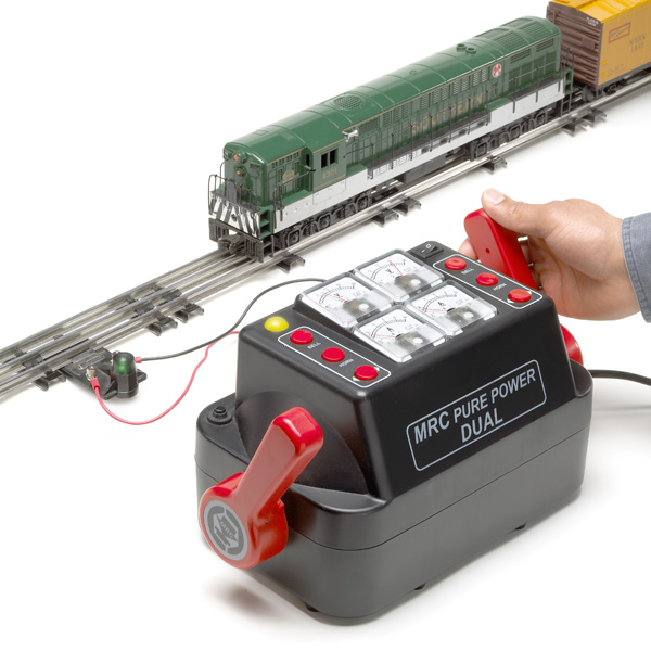
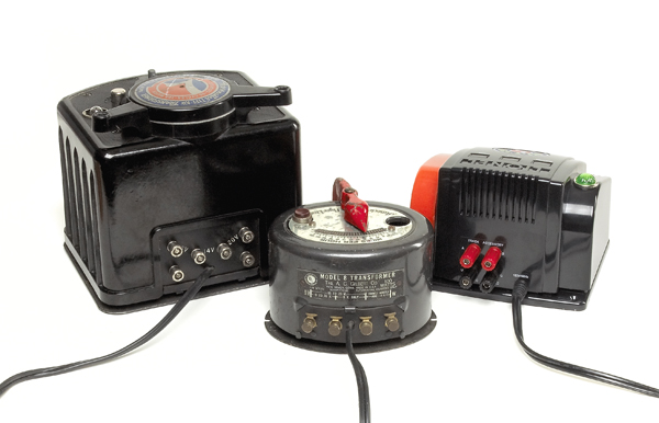
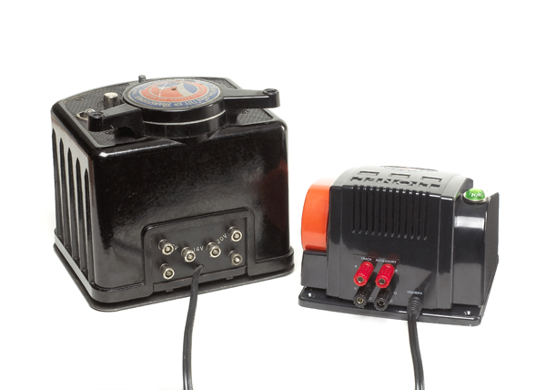
The three-rail O gauge toy trains sold in the United States are intended to run on approximately 5 to 20 volts of 60-cycle alternating current (AC). This is reduced from the standard 115-volt house current by a transformer. There have been many styles and configurations over the years, but they all do essentially the same thing. In fact, many transformers that were made a half-century ago are still in service. They are durable appliances.
All transformers have two or more taps or binding-post terminals on them, that can easily be connected to the track and various accessories. At least one will have a variable-voltage capability, controlled by the throttle, to modify the speed of the train. Others may provide constant fixed voltages for lights and accessories.
On transformers with more than two terminals, one is usually designated as the “ground”, or “return”, side of the circuit. Lionel often, but not always, used the letter “U” to indicate this terminal. Gilbert/American Flyer used “Base Post.”
This ground terminal is used in conjunction with all the other terminals and is supposed to be connected to the outside rails of three-rail track. Yes, the train will still run if you reverse the wire connections, but this distinction is important if you want to build a large layout without headaches.
The variable-voltage terminal represents the “hot” side of the circuit. It should be connected to the center rail.
The fixed-voltage terminals are also hot and work in conjunction with the ground terminal.
Using a common ground
When using more than one transformer on a layout, it’s recommended that the ground terminals on all of them be connected for convenience and efficiency. Larger transformers – those with more than one throttle – are connected this way internally. This is known as a “common ground.”
The common ground can make layout wiring easier and less expensive, because you’ll need to string only one ground wire instead of two. Track, lights, and accessories all can use this common ground return.
It doesn’t matter how many circuits share the same common ground, as all of them route their way back to the power source without interfering with each other.
Phasing transformers
When two or more transformers are used on a layout, they must be in “phase” with each other. Newer power sources – those with the three-pronged “grounded” or two-pronged “one way” plugs – are wired to be in phase by the manufacturer. However, older transformers – those with identical-size plug prongs – were not, so they must be put into phase with each other or a short circuit will occur.
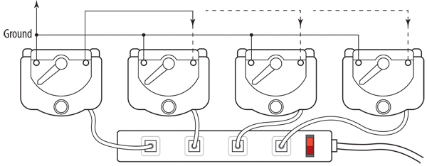
The process is really quite simple. First, wire all of the ground terminals together. If your transformer doesn’t have a designated ground wire or terminal, pick one.
Next, turn the throttles up, and touch a wire from the hot variable-voltage terminal on the first transformer to a similar terminal on the second. If the transformers are in phase, nothing will happen or you will see a tiny no-big-deal spark as the wire touches the terminal.
If you get a good spark, quite similar to a locomotive derailment spark, the line cord plug on one of the transformers must be reversed in the wall outlet. Test again to make sure there is no spark or, at most, a tiny spark.
Repeat this operation with all of the transformers until they are in phase with each other. It’s a good idea to use an outlet strip with an on/off switch so each of the transformer cords can remain permanently plugged in the correct way.
Wiring
Bigger is indeed better. Just as a large water pipe can handle more gallons per minute than a small one, heavy wire has greater current-carrying capacity than the thin stuff. Despite the temptation, this isn’t the place to skimp on quality in deference to price.
The idea is to have wire with more current-carrying capacity than you’ll need. Since some power is wasted by the resistance inherent in tinplate track, you don’t want to lose any more through the wires leading up to it.
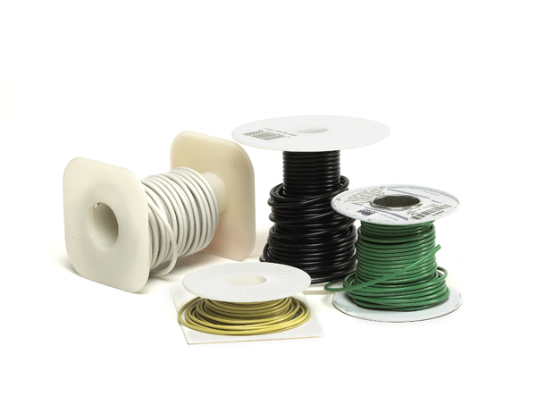
Whether you use solid or stranded wire is not as important as having a heavy enough gauge. Consider 12 or 14 gauge for bus wires (see no. 6 below). The minimum for track feeders is 16 or 18 gauge. For short runs to lamps and accessories, 20 gauge is adequate. Avoid anything smaller.
Purchase an array of different colored wires from a hardware store, auto parts store, or home center. Consistent color-coding of circuits makes troubleshooting and repair much easier. Pick a particular color for a certain application and stick with it.
The same theory holds for toggle switches –particularly those used in track circuits. Even though most trains run on 20 volts at 2 or 3 amps, it’s wise to buy heavy-duty toggles designed to carry household power loads of 115 volts at 10 or more amps. If you skimp here, underrated toggle switches can easily become overloaded, warped from overheating, or pitted by excessive arcing. Install good toggle switches, and they’ll still be working long after you’ve retired.
Making connections
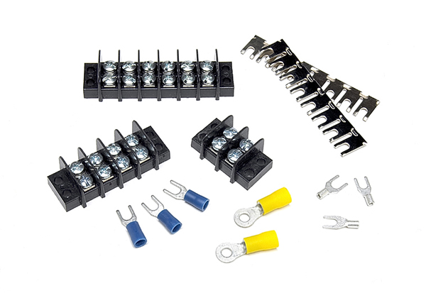
Take a trip through an electrical supply store and you will be confronted with a dizzying array of barrier strips, wire nuts, lugs, and fasteners that are intended to be clipped, crimped, twisted, screwed, snapped, or stuffed into place, with the purpose of making wiring jobs quick and easy. Some actually do accomplish that mission.
It depends on personal preference. While a couple of the CTT editors just love all of these plastic-and-metal connectors, I prefer making solder connections. They are permanent and impervious to oxidation. Learning how to solder has served me well over the years, and I highly recommend acquiring the skill. There is literally nothing among those quick and easy wiring aids that can’t be duplicated or surpassed with a 100-watt soldering gun and a spool of rosin-core solder. I won’t mention the difference in cost.
Control systems for multiple-train operation
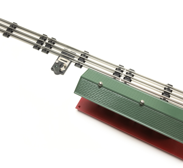
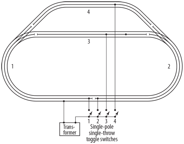
On a conventional-control layout, the two systems most widely used are “block control” and “cab control.” Block control involves only one transformer. The track layout is divided into insulated electric segments, or blocks, using plastic insulating pins in the center rails. Each block has its own on/off (single-pole single-throw or SPST) toggle switch. The operator keeps trains from running into each other by manipulating the current – turning it off and on – to avoid mishaps.
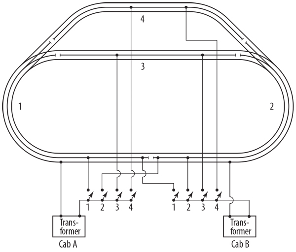
With cab control there are two or more transformers (or one transformer with two throttle handles) known as cabs, which can be operated by two or more people. The layout is divided into the same type of insulated blocks, but each block is connected to all the cabs through separate single-pole double-throw, or SPDT, toggle switches in each cab. Throw the switch to the left and cab no. 1 controls the block, throw it to the right and cab no. 2 controls the block. The cabs are electrically identical and autonomous, each capable of running the entire layout. As a result, the engineer behind each cab is able to take his or her train over the whole layout simply by energizing the appropriate blocks with toggle switches as the train moves throughout the layout.
SPST and SPDT – what’s in a name?
Single-pole single-throw and SPST are the technical terms used to describe a simple on/off toggle switch.
The single pole double-throw and SDPT designations mean that one terminal contact (the single-pole part) is connected to either of two other terminals (hence, double-throw), depending on which way the toggle switch is thrown.
Bus wires
Bus wires provide full power to all points on larger layouts. Think of them as extensions of the transformer terminals, hence the heavy-gauge wire used to create a run.
Bus wires usually run around the perimeter or down the middle of a layout, thereby allowing for splicing relatively short runs from the bus wires to track and accessories.
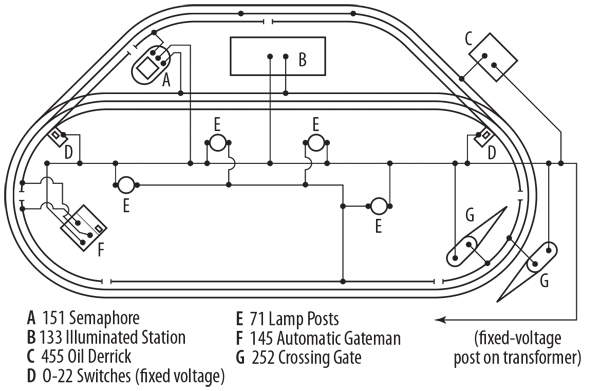
Using several fixed-voltage buses can be helpful. We find that 14 to 16 volts works for most accessories, and 18 to 20 volts works well for Lionel track switch motors.
Having a common ground bus can also be handy. That way, transformers around the layout can be connected to it instead of each other.
An alternative control system
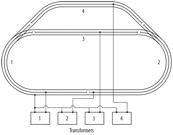
My favorite control system is the embodiment of simplicity and economy. It’s a variation on conventional block control that uses a battery of small transformers, one for each block, instead of one large transformer and a series of toggle switches.
With it, each block has its own individual speed control, whistle control, and reversing button.
Each transformer powers one block of track, nothing more. Other small transformers can be used for accessory circuits and other electrical requirements. Besides the versatility this system offers, the dollar savings can be substantial. Small transformers, those rated at 100 watts or less, aren’t highly prized by operators or dealers, so often they can be obtained at very reasonable prices.
Converting to command control
You can convert to command control at any time. If you eventually plan to use one of the electronic control systems, such as Lionel’s TrainMaster Command Control or MTH’s Digital Command System, you’ll discover that dividing your layout into blocks makes good sense anyway.
With each block having its own feeder wire, the voltage drop in larger layouts will be minimized. It also makes troubleshooting easier.
When you convert to the new system, all you have to do is turn all the toggles to the “on” position or to the same cab and then hook up the command-control components as directed. The old system remains as a backup to operate locomotives without command-control circuit boards.






How many amps should be sufficient for a bus?
Well done indeed! I am running 2 original ZW transformers in my train room. No command control. I just love the “old school”
well done
Yard switch wiring direction would be huge help. I have 3 legs off yard main and can’t get it right.
Very well done!
Very informative!
Enjoyed the article and was able to confirm a few questions I have had. However I would like to see this applied to the two rail S gauge guys like myself.