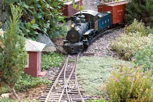
What railroaders call a “switch” is more commonly referred to as a “turnout” in model-railroading circles. This is to avoid confusion with the small electrical device we use to route power to various parts of our railroads. In this column, I’ll be referring to them as switches.
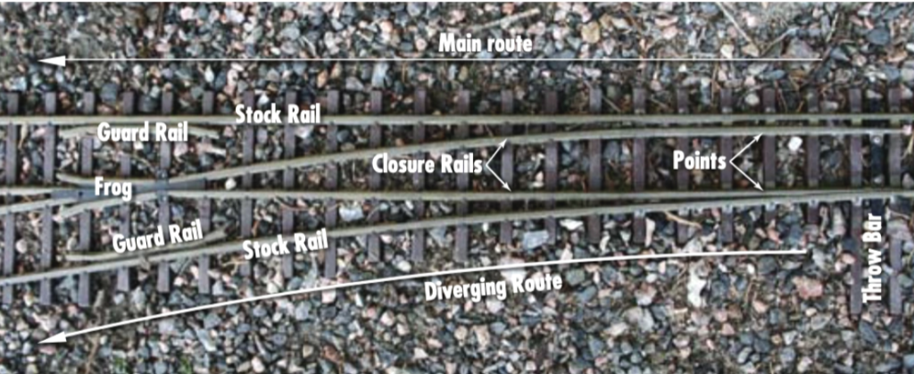
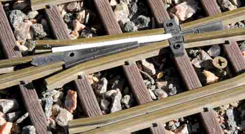
Let’s first talk about the components that make up a switch. The long, continuous rails that form the outside edges of the switch are called the stock rails. The movable parts that route the trains one way or the other are called the points. The throw bar ties the points together and controls their movement from side to side. The crossing in the middle where the rails meet is called the frog. The rails between the points and the frog are called the closure rails. The small lengths of rail on either side, opposite the frog, are called guard rails. These keep the wheels from “picking the frog” and heading the wrong way, leading to a derailment.
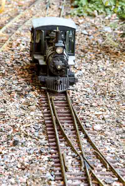
Sometimes, you’ll see switches referred to as “facing” or “trailing” switches. This refers to the direction the train travels over the switch. If it runs over the points before the frog (diverging), it’s called a facing switch (photo above). If it runs the other way (merging), it’s called a trailing switch. Trailing-point switches are less prone to cause derailments because the wheels never have to “choose” a path-they’re simply guided through on one set of rails.
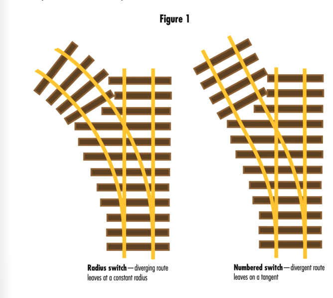
On a typical switch, the straight path is called the main route, and the path that curves away is called the diverging route. In a garden railroad, the sharpness of this divergent route is identified in one of two ways; either in terms of the radius, or by a number. Switches identified in terms of the radius of their curve are designed to fit in with the manufacturer’s sectional track of the same radius (see figure 1 above). For instance, LGB’s #16000-series switches are the same radius as their #16000 curves (roughly 3’10”), and form a 22.5° arc-the same arc as a curved section. Aristo-Craft’s 5′-radius switch [out of production–Ed.] is the same as their 5′-radius curved track, though the arc of the switch is shorter, meaning you need to install a “make-up” section on the end of the switch to make it the same length as the curved section. The short, 2′-radius switches made by LGB, Aristo-Craft, and USA Trains all fit the same space as their 2′ curved sections.
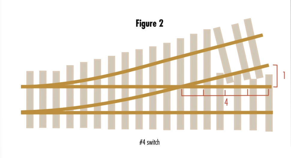
The other way switches are identified is by number: i.e, a “#6 switch.” The number indicates the sharpness of the switch (see figure 2 above). This is measured at the frog, and is sometimes called the frog angle. The larger the frog angle, the wider the switch. The number itself refers to the distance it takes for the diverging track to distance itself from the main track. For instance, with a #6 switch, the diverging track takes six units of length to distance itself one unit of length.
Special switches
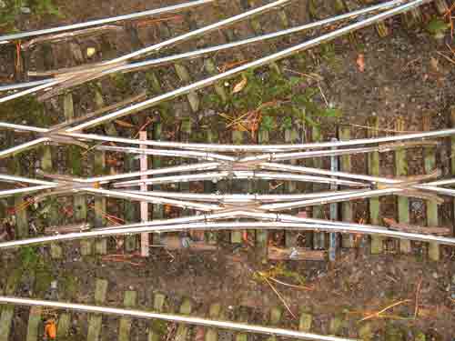
In addition to these “standard” switches, there are special switches used where space is at a premium. A wye switch, as it’s name implies, is shaped like the letter “Y.” Instead of one leg diverging and the other staying straight, both legs diverge in opposite directions. A curved switch is a switch built on a curve. Typically these are identified in terms of the radii of both curves, such as 4′-6′-radius curved switch. That means the larger radius is 6′, while the divergent route peels off at a 4′ radius. These usually aren’t “off the shelf” items, but some custom switch builders make them. A three-way switch is essentially a wye switch with a straight track going down the middle. The most confusing piece of switchwork is called a double-slip switch. This is where two tracks cross at an angle, but trains are able to either go straight across or move onto the crossing track. LGB makes the only commercial version of this switch, though it’s at a very tight angle.
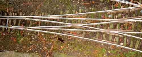
One other kind of switch that’s often mentioned-especially in terms of early railroading-is the stub switch. This early form of switch has no points. Instead, the rails leading to the switch are bent to line up with either the main or diverging track. This is where the term “bending the iron” comes from. Crews literally bent the iron rails to line up the switch. The advent of heavier trains and heavier rails brought an end to stub switches, though some examples do survive on preserved railroads, particularly narrow-gauge lines.
Throwing the switch
That brings us to the most important aspect of the switch-the switch throw mechanism. This is the mechanical device that holds the points against the stock rail, causing the trains to travel in the intended direction.
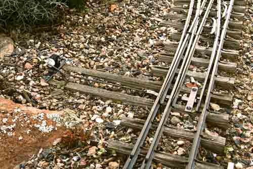
There are three basic kinds of switch throw: rigid, sprung, and rubber. The rigid throw moves the points against the rails and firmly holds them there. The points can’t be opened or moved without moving the switch throw. A sprung throw holds the points against the rails, but allows them to be opened by a train traveling through the switch in the “wrong” direction. Once the train passes, the points spring back to their original position. The third kind of throw-the rubber throw-is a variation of the spring switch. With this kind of throw, if a train comes through the switch with the points against it, it will merely push the points open to the opposite direction, where they will stay once the train has cleared.





A turnout is the prototypical term. The switches are the moving rails and the points are the sharp ends of the switches. Thus you throw the switches, not the entire turnout. Just as US modelers refer to them as “switches”, British modelers refer to them as “points”, but they are correctly “Turnouts”