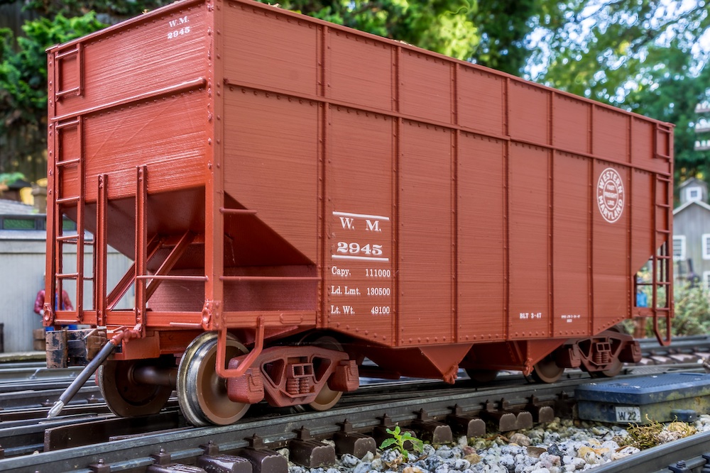
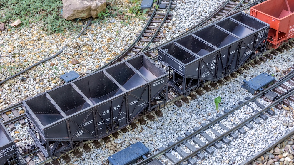
I model the Western Maryland Ry. (WM) from the 1920s to before the start of World War II. Appropriate commercial models of coal hoppers for my modeling era are limited in large scale. I was using LGB two-bay and Bachmann three-bay hoppers as stand-ins, but I wanted accurate, period-specific coal hoppers for my rolling stock fleet.
I turned to 3-D printing to create models that are otherwise not available. Over the last few months I created files, printed, and built different versions of the Vanderbilt, GLa, U-channel, and fishbelly hoppers that were operated by the WM and its predecessors during the era I model.
I also created some wood-chip variations of the U-channel and fishbelly cars. These cars represent the evolution of the hopper car from the turn of the last century into the 1930s. During this time the railroad was shifting from wood hoppers and gondolas to all-steel cars with greater capacity.
This series will take a look at the different cars I built. If you have access to a 3-D printer, the files are available on Cults3D.
Vanderbilt hopper cars
Designed by Commodore Vanderbilt, this hopper car design featured angled steel trusses instead of all vertical uprights. Eight hundred of the 50-ton capacity hopper cars he designed in 1901 were built by Cambria Car Co. of Johnstown, Pa., for the West Virginia Central & Pittsburgh Ry. These cars, numbered 5000-5799, were re-lettered for Western Maryland beginning in 1907 following its acquisition of WVC.
As built, the cars had vertical rods from the slope sheets to the frame corners. These were later replaced with corner posts to support additional grab irons that were required by the Safety Appliance Act. During subsequent rebuildings, WM replaced the grab irons with ladders attached to the corners. The majority of the cars were scrapped by the late 1920s, but about 50 continued in operation until the last was retired in 1939.
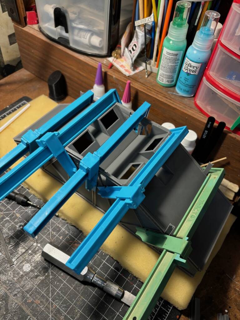
When designing the 3-D printed model, I made the sides, slope sheets, and underframe each as two pieces to fit the limits of a standard filament printer. I use Tinkercad to create my files, and typically use a scale of 1 mm = 1” to make it easier to design the files. This works out to 1:25.4 scale, so I re-scale my files in the slicer depending on what I am making. I built these cars in 1:29 scale, which worked out to a slicer rescale of 86%.
Since there were so many angles on this car, I found a side view image and created a .svg file that I could import into my design program. Once I scaled this imported file to the appropriate size, I was able to use it as a guide to make the side sheets, creating the appropriate angles and then adding all the trusses with correct spacing and angles.
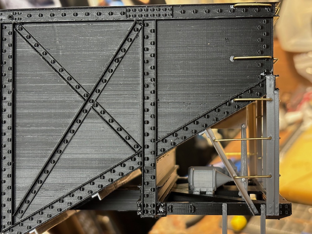
The first print of the sides had the center section angles and vertical channel as part of the print. After printing the first half, I decided to make the three center pieces separate because of the orientation and the quality of the print.
After printing the six basic components, I did a test assembly to check the fit and began assembling the parts. I glued the two side sheet sections together, using 1/8” styrene rod to join the two halves of the frame. After the side sheets were secure, I added the slope sheets and slope sheet supports over the bolsters, followed by the frame assembly.
This gave me the basic car that I could place on a pair of trucks to see how it looked. From there I added the corner posts, slope sheet supports, and crossties to the interior. The first car I built was the version with grab irons, which I made from .032” brass wire. I also added the K- type air brake components used on the full-size cars. Then I applied Ozark Miniatures ½” bolt castings to the brake beam.
Next, I installed the door assembly details. I used a piece of 3/64” brass rod for the control arm and added Ozark bolt castings to detail where the pivot arms met the door arms. Finally, I added Ozark Miniatures rod nut castings to the exposed ends of the control arm rod.
I again turned to 3/64” brass rod for the vertical brake staff. I also installed a brake platform, staff support brace, and brake wheel. The final details were uncoupling levers, which I made out of brass rod, and Ozark Miniatures air hoses and valve castings.
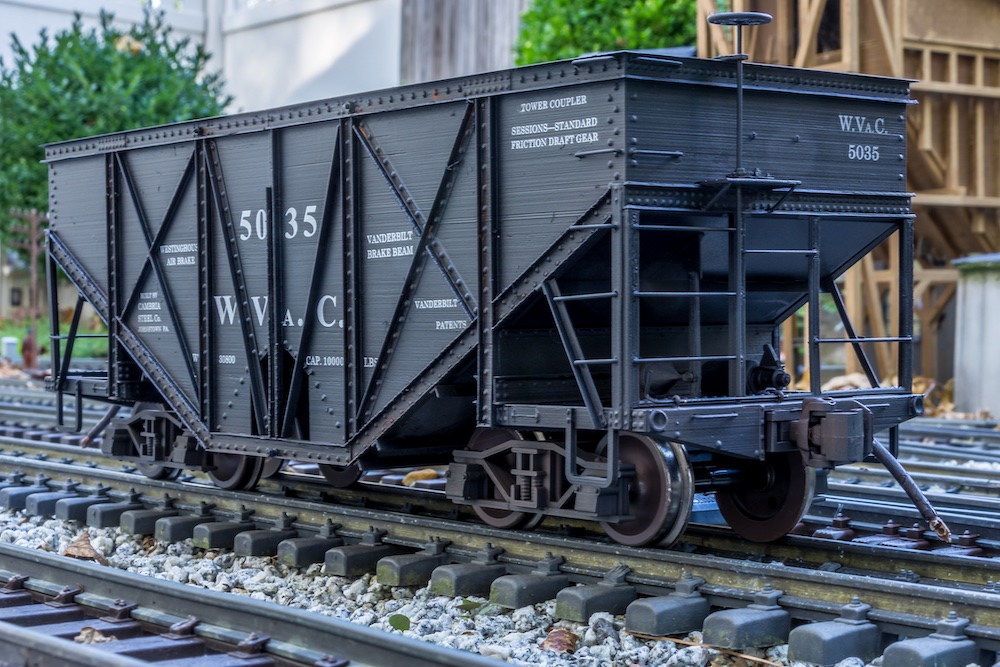
I printed the trucks and added metal wheels. I designed the car ends so the Kadee draft-gear boxes would press-fit installation. I equipped the car with Kadee center-set couplers.
Once the assembly was finished, I gave the car a coat of semi-gloss black to prepare it for decals. I used prototype photos as a guide to re-create the lettering for the WVC and WM cars. I designed the lettering sheet in Publisher and created a .PDF file. Then I sent the file to Shawmut Car Shops, the company I use to print decals.
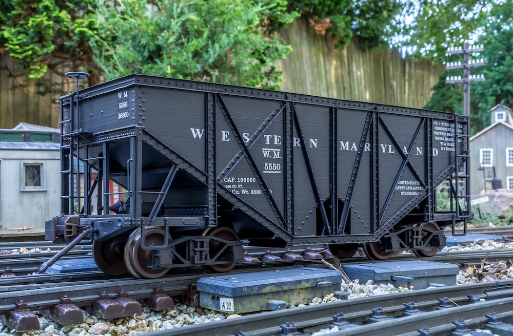
After building the first car, I printed a second version with ladders to represent the revised version after the second WM rebuild. This car was assembled the same way with the exception of fewer grab irons and the addition of the corner ladders. I lettered this car for WM.
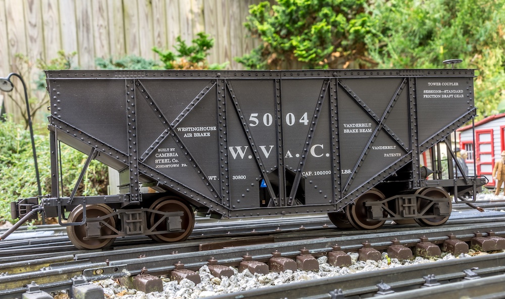
Even though it would have been early for my era, I decided to make a third car with the as-built corner support rods instead of corner posts and grab irons on the center of the ends. I lettered this car WVC 5004.


