


In the last issue we discussed how to use 3D-printer technology to make a part from files downloaded from the Internet (see part 1). In this installment we will look at how to create your own custom part. Modeling a part will take some work, some reading, and some head scratching but, in the end, you can create parts to your specific requirements. I will discuss making a window that I am going to use for my “new” office building.
If you have questions, please post in our related forum thread.
The design process
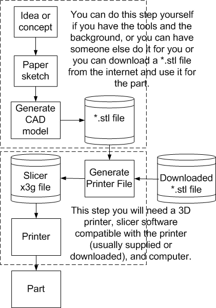
This is going to be a quick overview of the process necessary to make a part, from the design phase to the finished part.
Start at the top block beginning with your idea or concept (see photo 1). Make a sketch of the parts, with dimensions, on a piece of paper. This will help you later during the modeling process. Now, use your favorite modeling program to create your model (several are listed in the resources section). When you are finished, save the file or have it converted to an *.stl file, which is something the printer program can use. Using the printer program, download the file to the printer and wait for your model to appear.
Paper sketch
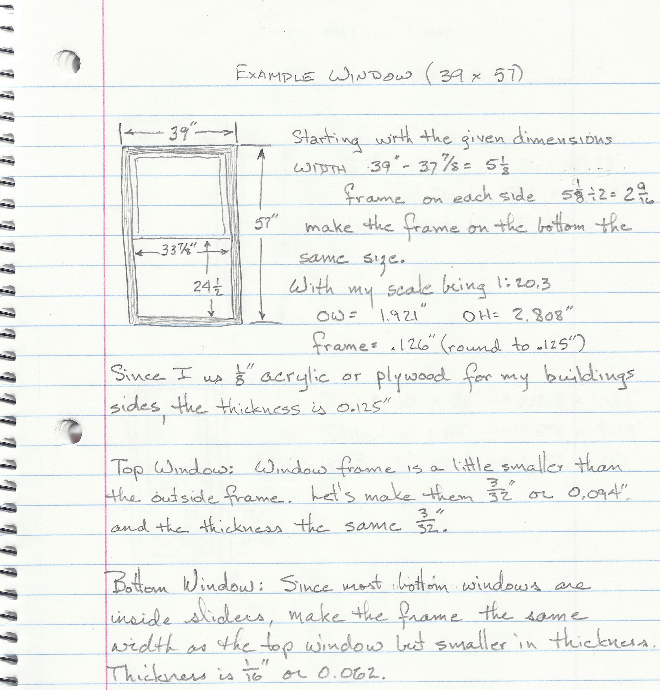
When I design a new part, I make a quick sketch of the dimensioned part with my scaled dimensions (see photo 2). I will keep this paper sketch and refer to it often while I’m modeling the part.
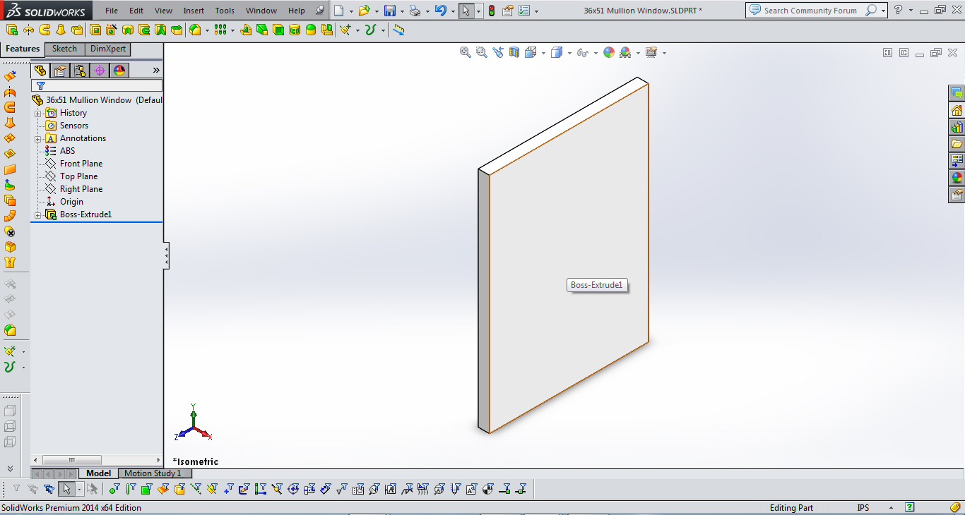
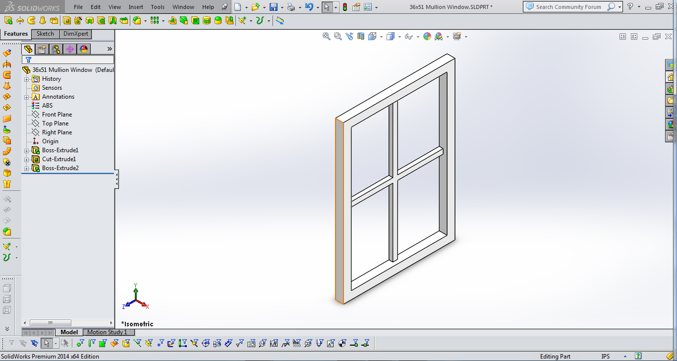
I use SolidWorks as my modeling software. Most modeling software will follow the same steps. There are only three basic things that you need to know how to do to make the window; create a rectangle, cut, or extrude.
The first thing that I will do is create a solid rectangle with the same dimensions as the outside of the window frame. These dimensions have been taken from my paper sketch. See photo 3.
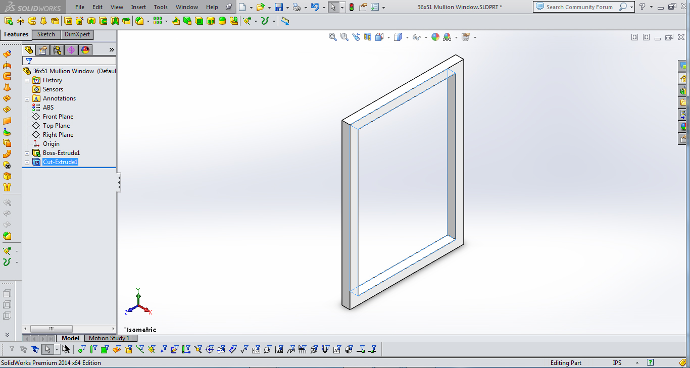
Next, I will cut out the section for the window, leaving just the window frame. See photo 4.
I will now extrude the mullions. Mullions are the cross members inside the window frame that divide the space into four small sections. Since I want them to appear as a true 3D window, I will only make the mullions half the thickness of the window frame. See photo 5.
Let’s take some time to explore the part a little more. You will notice the left-side tab called “Features.” There you will find “Boss-Extrude1.” This is the original rectangle that was created. Next you will find “Cut-Extrude1.” This is where I cut out the window area, leaving only the frame. Lastly you will find “Boss-Extrude2.” This is the mullions, which ordinarily complete the window. I am going to add one last detail by rounding the edges of the mullions.
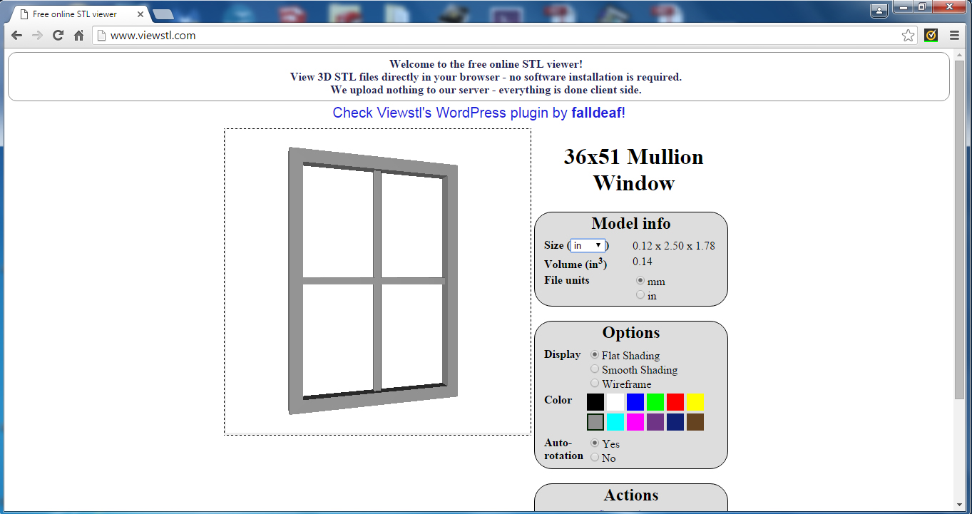
The part is now completed in the modeling software but we cannot use the SolidWorks part file. (This is true of any of the modeling programs that you would use.) I have to save the part as an *.stl file using the “Save-as” function and picking the stl extension from the pull-down menu. This is the file type that the printer software can use.
Once that is done, let’s use the program available on the Internet with the URL www.viewstl.com to see what we have. See photo 6.
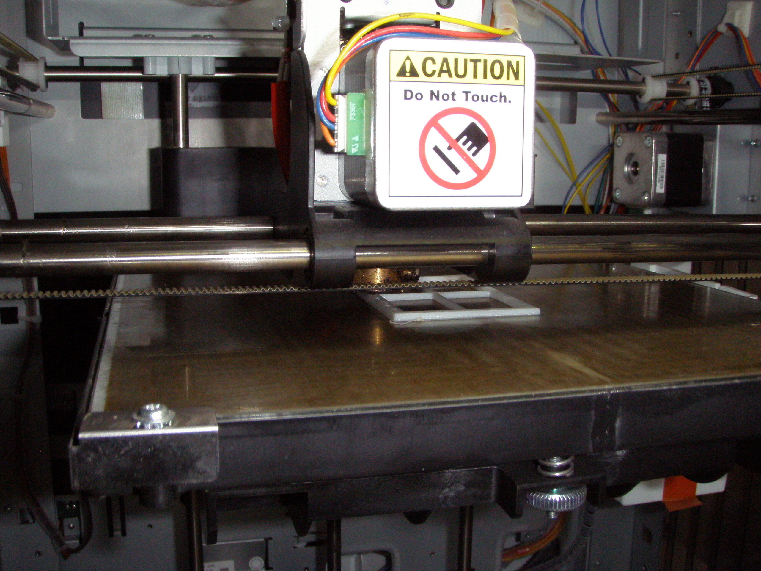
The model looks good so I went down to my local FabLab to get it printed. They have some very good machines at this location and I want some very good windows for my model. The printer I used was an XYZ DaVinci 1.0 from XYZ Printing. (http://us.xyzprinting.com/us_en) This is an excellent machine and I received excellent results. All windows are printed with ABS material to withstand the elements, and in white for a good base color. See photo 7.
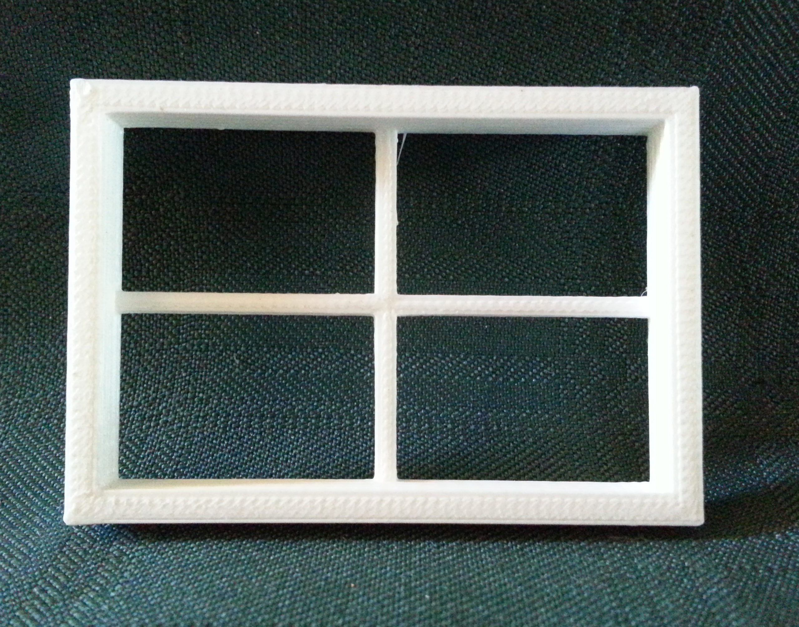
This is the completed window. See photo 8. Now I just have to make sure that it will fit my office-building model.
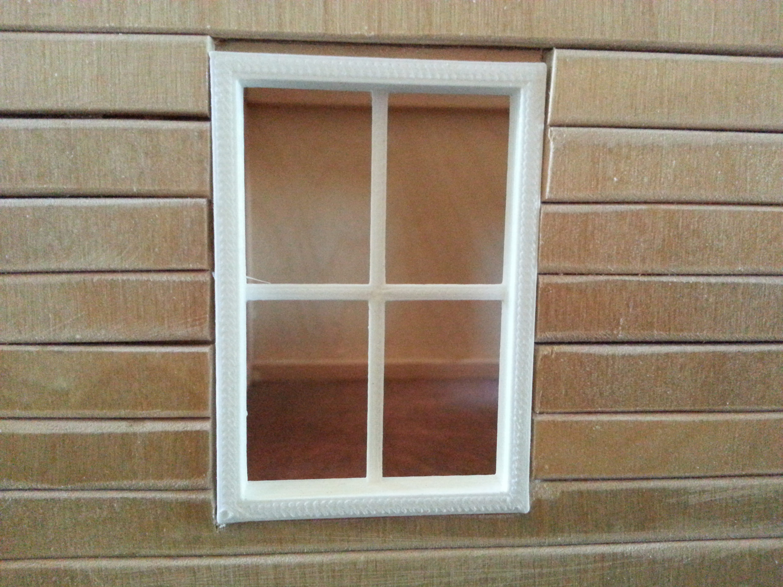
The fit is good. See photo 9. Now I can make all the windows that I need for any of the buildings where I want to use this window.
I have included the file, Window_mullion.stl for download. You are free to use this file for your current or future projects. (See download in gray box below.)
In the next article I will cover the printers that are available and some places that you might want to get to print out the part, or, if you know someone with a printer, have them print it out for you. I am going to concentrate on the ones available at my local FabLab. I am also going to cover FabLab and their mission, since these facilities are available at many locations throughout the United States.
Resources
3D CAD Modeling Software
SolidWorks – Expensive, but extensively used in the profession. www.solidworks.com
SketchUp Make – Opensource, good tutorials available on the Internet. www.sketchup.com


I’ve been doing windows and doors in Tinkercad for just over a year. By using rectangles and rectangular holes I’ve made two to four paned windows. Another useful feature is to build a complete wall with the window already printed.
Nice project but solid works?? 123d.com is free and does the same work.
I forgot that sketchup is very, very popular also.
You will typically go with what you know. I have used SolidWorks for years and have a legal copy. As I mentioned previously, there are a great many modeling programs, most free, that can and should be used. openSCAD, tinkerCAD and 123d are but a few and many more are being added yearly. The problem with most of these free programs is they are not as powerful as SolidWorks or ProEngineer, but we are not doing anything that requires all of the add-ins. Go with what you know; just make sure they put out an *.stl file. All printers can make use of this file type.