I wanted a reliable uncoupling method for my G-scale body mount Kadee couplers, with no moving parts or power requirements. I initially tried Kadee’s magnetic uncoupling system but found it wasn’t a perfect setup. It required the couplers be stopped precisely over the short magnet, and side-to-side movement of the cars due to slop in the trucks caused lateral misalignment of the coupler arms.

To solve my problem, I developed a system that uses what I call a “separator,” made from 3/8” x 5/8” aluminum channel screwed to the ties between the rails. One end is pointed and the other is tapered. The separator requires re-bending the trip pins on the couplers. Note: this system only works for Kadee couplers.
When a car’s couplers are pushed over the aluminum section, from the pointed end toward the tapered end, it will separate the two bent trip pins and uncouple the two cars. They will stay uncoupled while the couplers are on the length of the separator. Pulling forward, the car(s) are uncoupled, and will be left behind. The uncoupled car will remain with its coupler over the separator.
To re-couple the car(s), back the last car in the train into the car on the separator, push it past the tapered end, and pull forward. When the coupled cars are pulled forward, from the tapered end toward the pointed end, the separator’s tapered end will move both bent coupler trip pins to the side, keeping the cars connected.
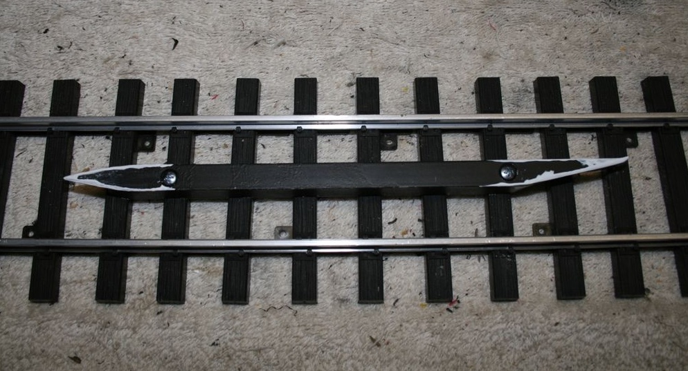
To construct the separator, make one end pointed and the other tapered (see photos). The length of the separator can be whatever you’d like; it just has to be long enough to easily stop the couplers over the uncoupler.
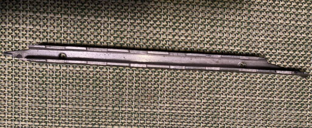
On the underside of the aluminum, I added 1/16”-deep notches to accommodate the ties (see photo above). The separator is screwed to the hardscape, centered between the rails so that the pointed end will fit in-between the bent trip pins when the car(s) are backed over it. The notches on the bottom of the separator match the tie spacing.
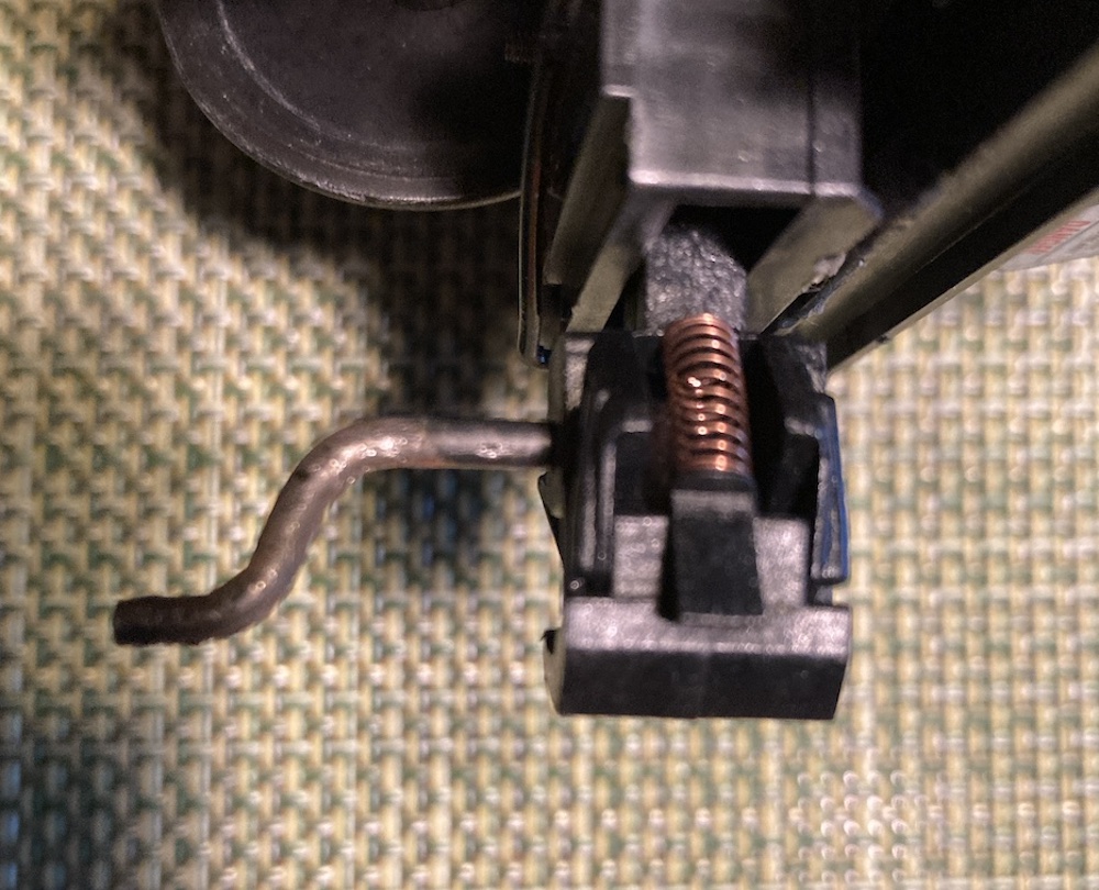
Bend the “U” shaped trip pin into a “Z” shape and reset it slightly off center. When the couplers are backed over the pointed end of the separator, one bent trip pin will move to one side and the other bent trip pin will move to the opposite side, thus uncoupling the cars.
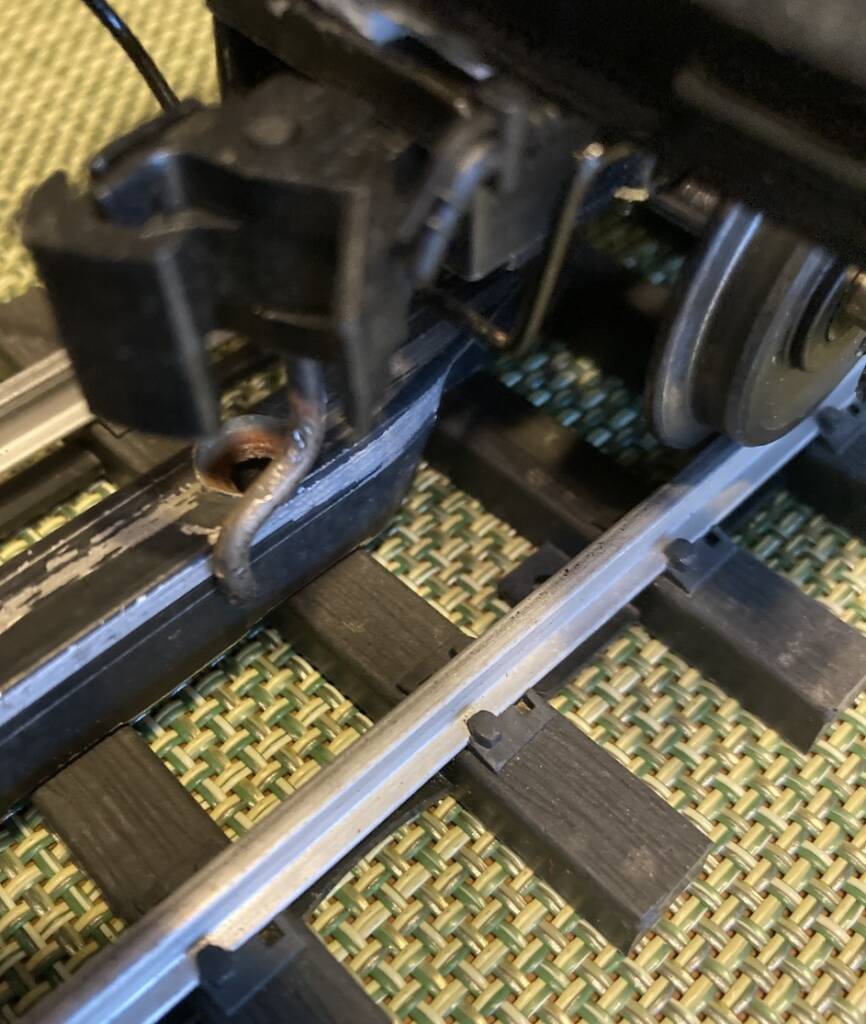
The method doesn’t require precision in locating the couplers over the separator or precise vertical height of the couplers/separator. It does call for a consistent height of the bottom of the trip pins, and it tolerates some lateral car movement (reduced by using shims on the axles).
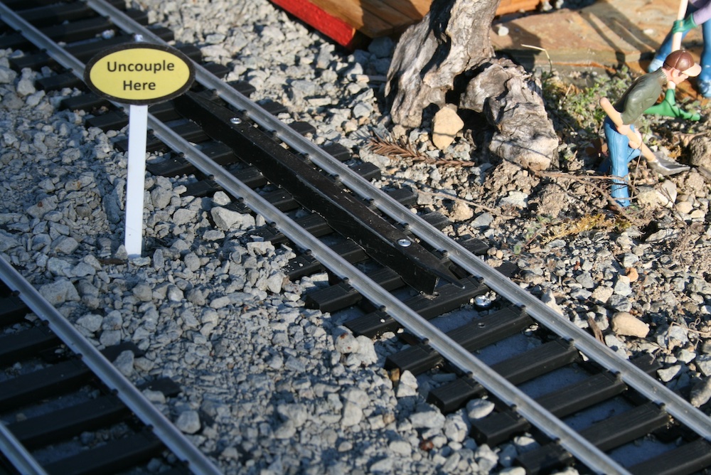
Nothing is perfect, but this system has proven to be 98% reliable outdoors. Maybe it can work for your railroad too.



After bending the trip pin it looks as though the pin will extend below the top of the track. Will that not catch and derail a car going over a turnout?