With our trackwork complete, we could now turn our thoughts toward wiring the Colorado & Pacific. Since ours was a small railroad, wiring would be simple. There were two ways we could set up the wiring. Despite the railway’s size, we could actually wire it in blocks for two-train operation. The mainline could be one block and the spur up the mountain another. This way, we could operate, say, a passenger train around the continuous loop while a small freight train took goods up and down the hill on what amounted to a separate point-to-point track. However, since we only had one electric locomotive, we decided to wire it up as a single block.
One of the biggest problems with a track-powered railway is maintaining electrical continuity across the joints, between the track sections. There are a couple good ways to remedy this problem. One is to solder jumper wires across each joint. Another is to solder the joint up solid. Since this was a small railway in a fair climate, we opted for the latter. On a larger railway, or on one subject to frost heave, soldering jumper wires across the joints will give the railroad more flexibility to move around as it needs to.
Soldering the joints
Soldering rail joints is a relatively simple matter with a small, hand-held butane torch. The rail ends must be clean. Since all of our track was new, this wasn’t a problem. We used a liquid flux to ensure the solder would flow properly. We covered the plastic ties adjacent to the joints with wet paper towels to minimize melting. You could also use wet ballast.
The secret to soldering is getting a lot of heat to the joint quickly, flowing the solder, and getting out. The heavy brass rails tend to suck up the heat, so this sometimes took a little longer than we expected. A few of the ties suffered a little damage, but when the ballast had been smoothed around the joints again, the melted ties were hard to see. We used jumper wires at the switches in case a switch went bad and had to be replaced. In that instance, jumper wires could be easily cut and the switch removed, whereas a soldered joint would be more difficult to undo.
Once the soldering was finished, we had a sort of monolithic electrical block. Because our track length was minimal, a single set of leads would accommodate the entire line. We soldered these leads to the rails near the upper end of the line at the patio, where our control station would be. We buried the line in the ground, with the ends of the wires sticking out where the controls would later be located.
Electricity
We wanted to keep the primary transformer in the house, out of the weather, and just run the low-voltage line down to the railway. An out-of-the-way place near an unused electrical outlet was found inside where the transformer could be permanently installed.
Unfortunately, the railway, at the bottom of the yard, was 40 or 50 feet away from the house, and there was no convenient way of permanently running an above-ground line down to it. On a trip to the hardware store we found some cable that was intended to be buried in the earth. This was heavy stuff that looked like it would last forever, so we bought enough for our job.
Upon returning home, we hooked the cable up to the transformer and ran it through a small hole in the wall, which was later caulked. Most of the distance from the house to the railway was covered by lawn. Burying the cable was a relatively simple matter of inserting a shovel about 6 inches into the turf, spreading the grass apart, laying the cable into the bottom of the split, then closing it up again. Even immediately after the cable was placed in the ground, its route was nearly invisible. We noted the position of the cable on our map for future reference.
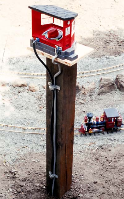
At the railway, we dug a hole in the ground and set a 4-inch-by-4-inch post in it. This would support our control platform. Since all of our controls amounted to simply an LGB #5012 speed controller, nothing too fancy or elaborate was called for. Simple is good in garden railroading. We attached a plain wooden platform on the top of the post, which was set at a comfortable height for operating from a lawn chair while holding a hot dog in the other hand, and our controller was mounted to it. The simple expedient of a plastic bag over the controller when not in use would protect it from the weather.
We ran the cable underground from the house to the post, as was the lead from the track. We brought both sets of wire up the side of the post and anchored them neatly and securely so they wouldn’t accidentally get snagged when we got up for another hot dog. Connections were now complete and it was time for our first test run, which was actually pretty exciting, given the amount of work we’d put into the project so far.