Then I remembered my aluminum side frames. I designed a bolster to fit the frames, built it, and put the truck under the front of the plow. Problem solved, or so I thought. I hope to someday submit the plow for consideration as an NMRA Master Model Railroader (MMR) project. To qualify, the plow needed a detailed braking system.
In the era I am modeling brakes are pretty simple. My research showed that early plows would have had what is essentially a parking brake. I decided to build a truck with attached brakes. I designed this truck from drawings by Robert F. Schlechter in Bruce MacGregor’s book The Birth of California Narrow Gauge. I sketched out the basic sizes for Fn3 scale (45 mm), but modified them to accommodate larger than prototype flanges and tight curves. See Figure 1. I then drew the side frames and bolsters in DraftSight. (DraftSight is a free product similar to AutoCad, and it saves files in DWG or DXF format.)
My intent for the rear truck—the focus of this project—was to make the metal work with hand tools, and design the more difficult detail parts using 3D printing.
The drawings included center marks for an 1/8” drill, where I would drill holes that would be filed out later. I printed the drawings out full scale, cut them out, and spray glued them to 3/16” thick aluminum. Photo 1.
I will admit to some “cheating,” as I used a bandsaw to rough cut the glued-on drawings from the main sheet. If you don’t have a bandsaw, a hacksaw will also work. I used a milling machine to rough off most of the material from the outside of the parts. Again, you could use a bastard file to rough off most of the material down to the lines. You could also use a rotary tool with a burr or a drum sander to remove material.
Note: You can NOT use a grinding tool on aluminum. Aluminum heats up excessively when ground, melts and sticks to the grinding wheel. A drum sander with a coarse grit works while the grit is new, but it will quickly dull and become coated with aluminum.
An optical center punch is a neat little tool to help you drill accurate holes. Photo 2. I designed the center marks for an 1/8” hole, drilled with a 7/64”, and considered drilling with a 3/32” drill instead to avoid drilling over the lines.
Drills are not terribly accurate tools, even with an accurately punched center mark. They have a tendency to deflect under pressure. If the cutting edges are not exactly the same angle, the length and sharpness of the drill will want to deflect as well because one cutting edge is doing more work than the other. I drilled larger holes where they would fit. Photo 3.
If you have never spent much time filing, the best way to learn is to try this technique. Take a round bar, 3/4” in diameter, about 2” long, put the piece in a vise and file the round bar into a square bar using use a flat bastard and a machinist square. Use two hands when filing, with one on the handle (never use a file without a plastic or wood handle). One or two fingers of the other hand pushes down on the front of the file with equal pressure. This part can get tedious, as there is a lot of filing. Photo 4.
I used a flat and knife edge needle file to file out the insides of the frames, and a small flat bastard file to finish up the outside angles on the frames and the steps of the bolsters. Use the top of a vise as a guide for filing to the lines. When your file hits the jaws of the vice, it will slide easily because it is not cutting metal. Photo 5.
The ends of the bolsters, the journal box fronts, the brake beams, and the top of the bolster were designed using a solid modeling software, then 3D printed. Figure B. I suggest using Autodesk Fusion 360, because it’s free to hobbyists and there are lots of tutorials (I like Lars Christensen’s work). Photo 6 shows some of the parts after coming off the printer.
Of course, the process of learning a software package like Fusion 360 takes time. Once you have enough experience, though, you can make just about anything. I’ve made a Billmeyer & Small passenger truck that is just about ready to bring to market. This would not be possible without 3D CAD software. See more at my blog at bigstackslittlelocomotives.wordpress.com.
The bolster is made up of several different pieces: the top (3D printed), two bolster ends (3D printed), two outer aluminum pieces, and an aluminum center piece. The top is screwed on, but the two outer aluminum pieces are designed so that I can take the truck apart if needed.
Filing these outer pieces to fit inside the side frames takes a bit of time. Likely you will find that as you file the steps of these outer pieces, they will be angled one way or the other. If there is an angle, the finished bolster won’t sit properly in the frame. Every now and then, take the piece out of the vise and look at it from the end to check the angle.
Once the outer bolster parts fit within the side frames, fit the end caps. Check to see that the outer bolsters (with the end caps on) fit in the side frame. Photo 7. You may have to file the frame a bit to allow the bolsters to be wide enough apart.
The ends of the outer bolsters were drilled and tapped 0-80 NF. Screws go through the undersides of the bolster end caps and through the aluminum outer bolsters to hold the everything together.
The center bolster piece is 1/2” thick aluminum filed to .44” thick. The top of the center bolster must be the same height as the outer bolsters, so the outer ends of the center bolster must be filed to match. Figures 3 and 4. The “spring” is a piece of ¼” automotive vacuum tube. Photo 8.
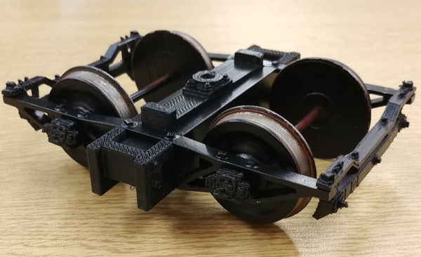
I am happy with how this project turned out. Photo 9. This project develops a lot of skills and if combined with turning your own wheels (GR December 2018, get a PDF of that article here) makes you ready to do take on nearly any project.