Stoneworks
PO Box 190
Shell Knob MO 65747
Price: $45
Website: www.RRStoneworks.com
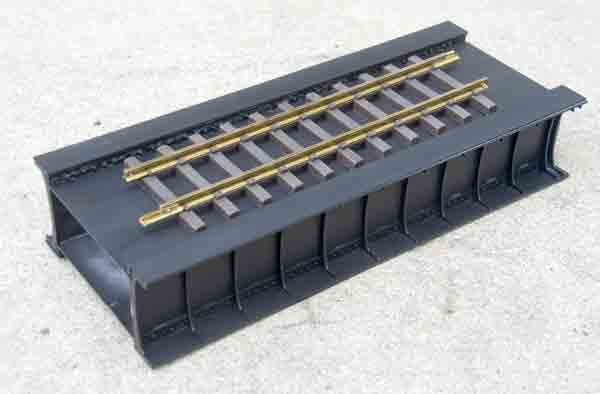
Laser-cut styrene kit for one 15 1/2″ section of a box-plate-girder bridge (#4250). Dimensions: length, 151/2″; height, 3″; width, 6 1/4″
Pros: Realistic appearance; sturdy, once assembled; modular construction makes adding additional sections easy
Cons: Rivet-detail pins difficult to keep in place during assembly; not suitable for curves under 20′ diameter (10′ radius)
Stoneworks’ box-plate-girder bridge is based on a fairly common style of railroad bridge. At 151/2″ long, it scales to a span of 31′ in 1:24, though it is certainly suitable for all common garden-railroad scales. According to the literature that came with the kit, spans of this construction ranged anywhere from 15′ to 100′ or more. Construction is such that additional spans can easily be added.
The kit consists of a bag of laser cut, .060″-styrene parts, a bag of brass pins for the rivet details, and a small file to knock the burrs off of the styrene (a side-effect of the laser cutting process.) I didn’t notice a lot that needed to be sanded, so I just ran over the edges of some of the more egregious offenders with the edge of an X-acto knife.
Instructions are simply written, though I wish the photographs showed more in-progress steps, as opposed to showing different angles of the completed sides to illustrate the points. Having said that, it’s fairly intuitive, so there wasn’t much ambiguity.
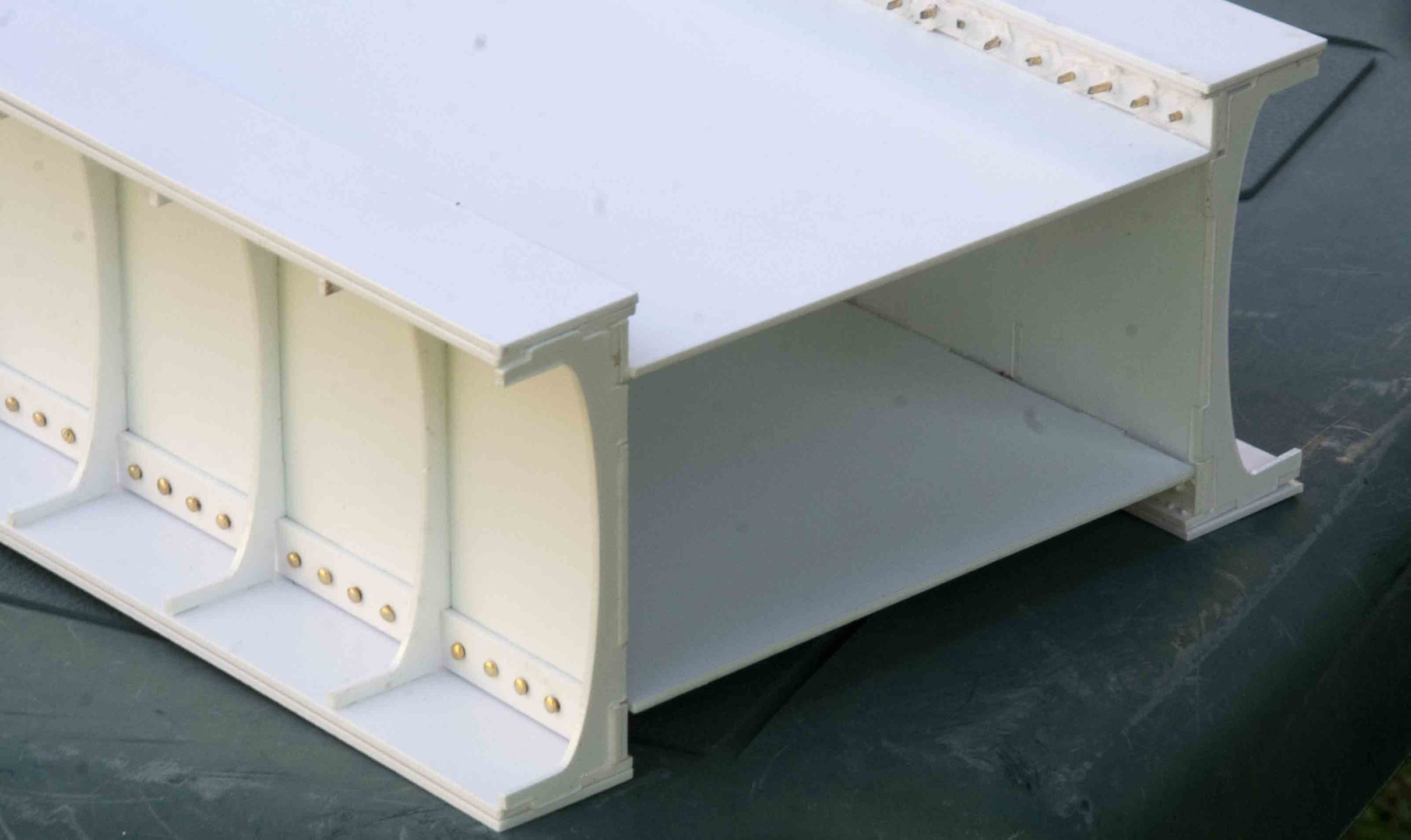
The most difficult part of the assembly has to do with installing the rivet detail into the plates. There are two pieces with holes drilled in them—the plate and a narrow strip. The idea is to line up the holes, use solvent cement to glue the strip to the plate, stick the pins in the holes, glue them in with CA cement, then cut the backs off the pins.
There were a few problems with this. First, the holes are large compared to the diameter of the shafts of the pins, resulting in loose fits. They flop around, and you’re relying on the CA to hold them in place. Second, cutting off the backs of the pins invariably broke the bond holding the pin in place, sending me scrambling to find the pin on my workshop floor. (Fortunately, extras were included.) After the first 15 pins, I was quite frustrated. Ideally, this problem might be solved by making the holes smaller, so that the pin is a press fit through the styrene sheet. That might not eliminate the need for glue, but it would certainly keep things in place while cutting off the backs.
Alas, I had to work with what I had. Instead of using solvent cement to bond the thin strip to the plate, I used double-sided tape from the craft store. (“Recollections” is the particular brand I bought, though there are others.) This did two things—it not only attached the narrow strip to the plate, but the tape covered the holes so that, when I pushed the pins through, it held them in place. Once all the rivets were in place, I went along the back with copious amounts of CA cement and glued them in. Then I could cut the backs off of the pins without much fear of the glue bond breaking. I might be tempted next time to use a different kind of glue, such as OmniStick or E-6000, drawing a bead along the back prior to inserting the pins, letting that set, then going back and cutting off the excess.
After that, the rest of the assembly process went without incident. The instructions recommend using solvent cement. I used that for the ribs on the outside but, for the interior joints holding the sides to the base, deck, and rectangular stiffeners, I used OmniStick, as I wanted something thicker that would grab onto the sheets and give a stronger bond. You could also use a solvent cement in gel form, such as Testor’s model glue. I know OmniStick holds up well outdoors and I had it on hand.
It only took me a few hours to build a section of the bridge, and that included the extra time working with the rivets. You could probably build a 4’–5′-long span in a matter of an evening or two in the workshop. Stoneworks recommends using a large Styrofoam insert between the side plates to join multiple sections, possibly augmenting that with a plate-and-screw reinforcement.
The way the bridge is constructed, the track sits on a deck about 3/8″ below the top of the side plates. This allows you to place some ballast on the deck, if so desired. On the other hand, this limits the amount of curve you can put on the track going over the bridge. They list it as a 20′ minimum diameter. That suggestion is based on “typical” tie lengths. If you’re using longer ties (such as 1:20.3-scale ties) that diameter will increase. This probably isn’t the product to use if you need a bridge on a tight curve.
That having been said, it wouldn’t be much of an issue to cut a few inches out of the width of the deck plate, bringing the sides closer together, then laying the track on top of the girders for bridges with tighter curves. That configuration would look pretty slick, as well. Perhaps that might be a future option for Stoneworks.
If you are going to curve the track over the bridge, you’ll need to trim the ends of each section to an angle to match the curve. Stoneworks suggests using a bandsaw to make this cut. You’re on your own to figure out what the angle needs to be.
Overall, I’m impressed with this kit. It goes together fairly easily (once the rivets are sorted out), and the curve on the ribs gives it a bit of elegance that you don’t find on many bridges. While I currently have no place on my railroad for this bridge section, it will look just as good sitting on a shelf beneath one of my locomotives.