Q: I have a Walthers gas plant kit (item 933-3104) and gas storage tank kit (item 933-2907). I want to use these to model a coal-gas plant. Do you have any drawings or pictures of such a plant that I can model using these kits? – Thomas Lauritsen
A: To help you model a coal-gas plant, I can do you better than a few photos and drawings. Jeff Wilson’s book Industries Along The Tracks 4 (available from the Kalmbach Hobby Store) devotes an entire chapter to modeling the coal-gas industry.
The coal gasification process dates from the late 1700s in France and started to spread across the United States in the early 1800s. By the 1860s, most towns of notable size had a gas plant of their own to supply gaslights on the streets and in homes and businesses. At the industry’s peak, more than 50,000 coal-gas plants were in operation across the country.
The conventional coal-gas process involves heating bituminous (soft) coal in an oxygen-free vessel called a retort so it would not burn. The heated coal would release flammable hydrocarbon gases that were collected and purified, then delivered to streetlights and homes via pipeline. In the process, the coal would lose about 40 percent of its mass, becoming coke, a valuable byproduct that could be burned to heat the retorts or sold for a profit. The plants also produced other valuable byproducts including ammonia and coal tar, used to make creosote, pitch, and other products.
In the 1870s, a new process called water carburetted gas came along. Since water carburetting plants were cheaper to build and more efficient than the old type of plant, and water gas burned more efficiently, this process overtook the conventional coal carbonization process by 1911. However, water gas was more expensive to produce and didn’t produce valuable byproducts. So many gas plants made both kinds of gas, using the coke produced by the conventional method to fuel the plant and selling both products as “mixed gas.”
The electric light started to make gaslights obsolete around 1900, but since the production process was more efficient by then, the industry easily shifted to supplying gas for cooking and heating. This lasted until World War II, which saw new pipelines laid from the oil fields of the Southwest to big cities and the coasts. Natural gas, once a waste product burned off at the wells, became cheaper to supply to the cities than coal gas, and coal-gas plants started to close across the country in the 1950s. The last coal-gas plant, in Indiana, closed in 1966.
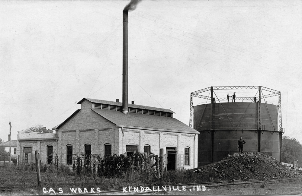
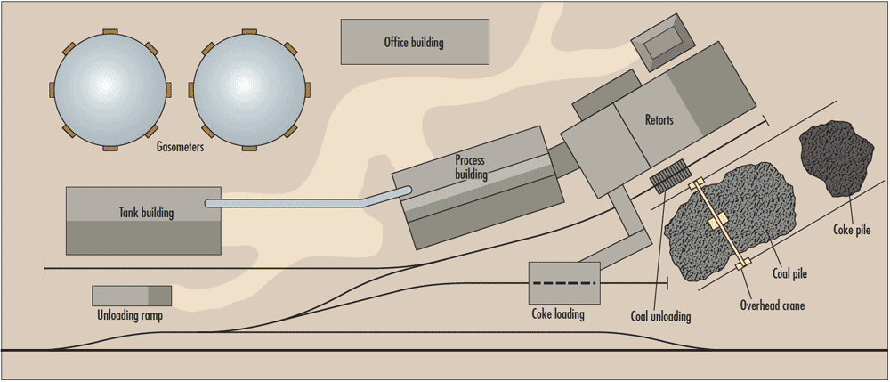
Typical coal gas plants were made up of one or more industrial brick buildings housing the processing and cleaning equipment; at least one tall smokestack; a big coal pile and conveyors for moving it to the retort or processing building; and the gasholder. Also known as a gasometer, the gasholder was a large, cylindrical tank made of several telescoping sections, enclosed by a structural steel framework. As gas was added to or extracted from the tank, the telescoping tank would get taller or shorter to maintain gas pressure and prevent it from mixing with air. Gasholders are the most easily recognizable feature of a coal gas plant, and a tank painted with the name or logo of the gas company would be an eye-catching scenic landmark on your layout.
The Walthers storage tank you have is a perfect model of a gas holder. However, Walthers item no. 3104 is a tank car loading platform, as would be found at an oil refinery. To model the buildings of a coal-gas plant, I would recommend something like Walthers’ Brickworks (item 933-4102), their Brick Millworks (item 933-3907), or something custom-built from Design Preservation Models’ Modular Building System (such as item 35100).
Send us your questions
Have a question about modeling, operation, or prototype railroads? Send it to us at AskTrains@Trains.com. Be sure to put “Ask MR” in the subject.


