Q: I am researching transition era railcar brakes. Were there books written on the subject, and are they still available for purchase? – Ron Buddemeier
A: The most complete and detailed reference for transition era railcar brakes is the one used by the railroads themselves – the Car Builder’s Cyclopedia of American Practice. This weighty tome, updated and issued every few years, includes prototype car photos, dimensioned blueprints, advertisements from car makers, and diagrams of car equipment from air conditioners to brake valves.
Since the CBC was a limited-run book that was rarely preserved when a new edition made an old one obsolete, copies are few and far between. So if you can find a copy from the year range that you model, it will likely be pricey. And since it was meant as a reference manual for railcar mechanics who already knew how brakes worked, it might not even have the kind of information you’re looking for.
If what you want to know is how to model transition era railcar brakes, I can help you out. The earliest freight cars had manual brakes. These were mainly used as parking brakes, since a brakeman had to turn a brake wheel on the roof to set or release them.
The first air brakes, applied and released by air pressure from a reservoir on the locomotive, were invented in 1869 by George Westinghouse. Though they were an improvement over manual brakes, they had their own problems. They were only effective for trains of no more than 8 or 10 cars, they were prone to cause coupler slack action when applied or released, and they couldn’t stop a runaway car separated from the engine.
A big improvement in safety came with the development of the automatic air brake in 1873. In this system, every car was equipped with its own air reservoir, pumped up by a compressor on the locomotive. If air pressure in the train line dropped, a device called a triple valve would automatically open, sending the air in the reservoir to the brake cylinder, applying the brakes. Now, if a coupler broke and part of the train separated from the locomotive, it would come to a stop on its own.
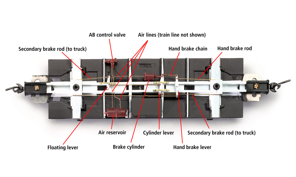
The first version of the automatic air brake was called a “K brake” after its type K triple valve. After World War I, the railroads started looking for a replacement for Westinghouse’s venerable K valve. The result was the AB valve, developed jointly by Westinghouse and New York Air Brake (NYAB) and adopted by the Association of American Railroads (AAR) in 1934. The AB braking system added more safety with a two-part reservoir consisting of an auxiliary tank and an emergency tank. If you have a detail part of a tapered tank with a bolted ring around the middle, as in the picture above, that’s an AB double reservoir. This is the kind of brake system you’ll find on freight cars of the transition era you model, since the AAR banned K brake equipment from interchange service in the 1940s.
On our website, Trains.com, I wrote a “Sketching With Steve” column that goes into more detail on how to model transition era railcar brakes. Also, the National Model Railroad Association (NMRA) has a handy downloadable data sheet with more information about the history and operation of prototype brake systems.
We have published a few how-to articles in the past two decades that include installing brake details on freight cars. Check out “Underbody for a UP caboose” by Andy Sperandeo in our August 2005 issue and “Upgrade a plastic freight car kit” by Mont Switzer in August 2016.
Send us your questions
Have a question about modeling, operation, or prototype railroads? Send it to us at AskTrains@Trains.com. Be sure to put “Ask MR” in the subject.


