Every year starts with lights, and then trees. And upon the tree are decorations. Then there are tracks. And upon the tracks are trains. With the trains come happy children, followed by basement layouts.
My grandkids have loved trains since before they could walk. The first train was a circle of track on the carpeted floor around the tree. Later a second circle was added for another little engineer. It was evident that trains were going to be around grandpa’s tree for a long time.
As everyone grew older, I thought “you can do better than this.” A simpler layout, more complex was needed — one that was more robust than the carpet layout. The challenges were first identified:
- It must have a small footprint and easy assembly.
- It must be lightweight and easy to set up and store.
- It must be elevated to accommodate and hide the tree stand legs.
- It also must protect trackage, scenery, wiring, illumination, and provide space for sound.
- Scenery must be robust, non-shedding, inexpensive, and removable.
- Options for bay window, free standing, or black jack table.
The footprint
Although a circle is the smallest, an octagon is easy to build and provides more opportunity for scenery and expansion. Using a modular design accommodates tree, floor, window, and table installations. If desired, it can be a one-piece top, seamless construction. Heavier and bulky, it rolls slowly Flintstone style. All have removable electrical and speed controls.
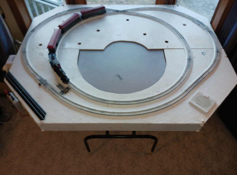
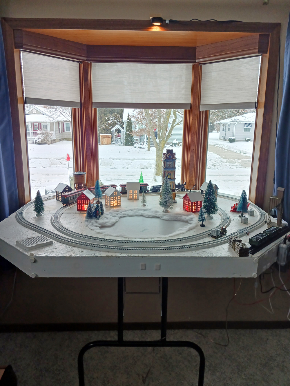
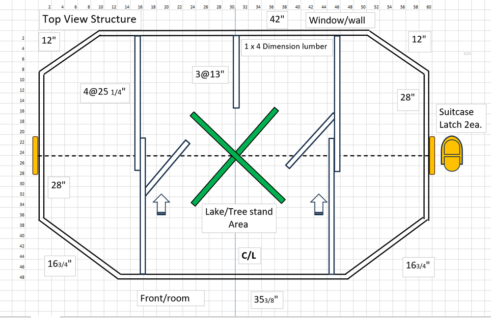
The 4’ x 4’-10¾” stretched octagon fits the track plan also allowing clearance for future bay window installation.
Caution: Your window trim width will determine the width and shape of your layout. Adjust dimensions accordingly. The top is ¼” x 4’ x 8’ OSB (chipboard). For the sides I used dimension lumber, 2 each of 1” x 4” x 8’ to accommodate the height of the tree stand legs. If your tree stand has a higher profile, don’t worry. We will accommodate for variations when we cut the center hole. Use scrap and/or additional lumber for internal support to the floor for bracing, seam alignment, and roadbed.
Pre-assembly
Most lumber stores will do some of the cuts you need on the 4 x 8 OSB top for transport. Ideally you want to end up with 2 pieces of 5’ x 2’ and a 4’ x 3’ waste for 2 modules, or 1 piece of 5’ x 4’ and a 4’ x 3’ waste for seamless design.
Caution: The finished size is 4’ x 4’10¾”. Then cut perimeter boards ends mitered @ 22-1/2 degrees, to length.
Start with the longest board, adding 2“ (waste) to the measurement from the end of the board and mark. Cut a 22½ degree angle as per caution. Cut 2” waste to 35” outside good dimension. If both sides of the stock board are reasonably good, your job becomes easier. You have made two cuts. Rotate or flip for proper angle, measure, cut, and continue. If not, the process is similar except more cuts and little pyramid waste pieces.
Mock-up
Place the OSB board(s) good side down on the floor and make sure the factory edges are together. Arrange the mitered boards with the good side out. Using a ruler or straight edge, span the mitered joints equally on top, centered on the back of the inside corner, then pencil a line across the top of the boards. This will give you the maximum joint strength angle for driving wood screws.
Start with the short corner diagonal boards only. The pilot hole bit diameter should be smaller than the no. 8 screw diameter. Start at least 1” back from the corner of the joining edge, using the angle drawn, to drill the countersink pilot hole. Drill one top and bottom on both ends. Eyeballing the screw angle is ok; maintaining 1” entrance hole distance from the cut edge is more important for strength. Repeat this on all four short corner boards.
Assembly
Pine is a soft wood and strips easily. That is why I am only drilling the corner diagonal board with the countersink pilot bit holes at this time to allow for assembly adjustment. No. 8 crosshead, countersink, wood screws are recommended.
I started with the diagonal corner board with the screw closest to the OSB top since it is square and a mating surface. I aligned it with a longer side board and hand-tightened the screw. The screw’s length should allow for the head being recessed slightly and as to not exit the mating board. If this happens, remove it, and install a shorter one. I repeated the process only for screws adjacent to the OSB board. Then proceeded to install the remaining screws. If there are minor gaps at the joints try alternating pressure between top and bottom screws. If the gap is not visually acceptable you can re-cut or sand edge heel to 22 degrees. Align the assembly to OSB for orientation. For ease of handling, you can cut the side boards of the assembly in half to make the 2 modular assemblies now or proceed skipping the backset step for a more precise method. Next, backset the OSB seam to the width of the saw blade that will be used to cut the perimeter boards into separate modules at final assembly.
Mark and cut OSB(s) corners to fit your 4’ x 4’-10¾” assembly. Flip the assembly top side up and apply wood glue on the top half of the full assembly. Install and align the OSB, good side up, to edges while maintaining seam backset. Flip and tack down the OSB top with 1” finish nails or a brad nailing gun. Flip top down and hand tighten all the screws. Repeat this step for the final half of assembly, maintaining the backset. Allow the wood glue to dry. Congratulations! You now have a stretched octagon.
Reinforcement, divorce, and hardware
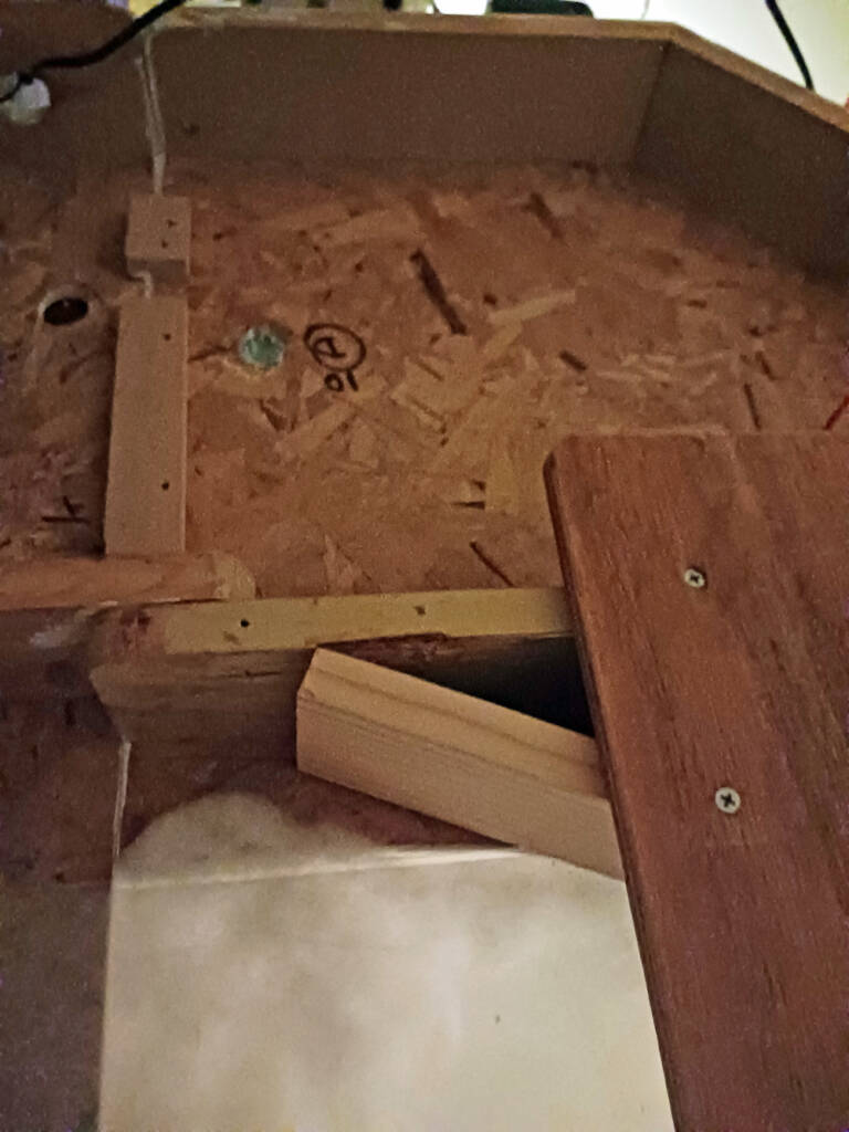
Reinforcement is mostly dependent upon your tree stand configuration and whether your layout will be on the floor, window, or free standing. Feel free to vary your own configuration. I will continue with my evolution of design which works for all three. The idea here is to provide minimum support but maintain sturdy trackage and joinery. The front module should be free of supports that interfere with the tree stand while sliding it in toward the tree after decorating.
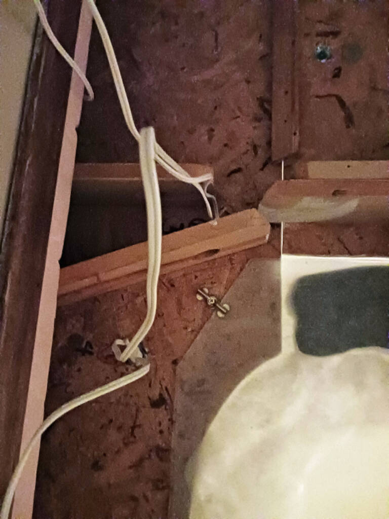
Let’s start with the tree stand. Most are of the X design so you need to know the distance from the back wall to center of where the tree will reside. Some prefer a distance smaller than the radius from the wall for large trees so it is less intrusive. Once that is determined, and mark the center of the back wall underside orientation.
Next center your tree stand over the mark. Measure up the stand leg to 3” height from the OSB and mark. Measure from that mark to the center mark of the tree stand. That measurement will be the minimum radius of the hole (lake) needed for tree stand clearance. Next mark the tree stand footprint on the OSB with painters tape. Now you know where your reinforcement material and utility holes can go. I mitered scrap pieces of the 1 x 4 boards to fit, rounded the edges, glued them to the OSB along the top and perimeter, and finally finish nailed them.
The module joinery contains 3” overlapping reinforcement tongues on both sides for easy alignment and support of the module. A ½” x 2” lap joint board can be attached underneath the module OSB seam if desired. Using your predetermined radius, cut the hole, check for the fit of your tree stand, make allowances, or shape the lake profile. While you have your saber saw out you can cut a 4” circle for a speaker and grille for train sounds. Little engineers like that.
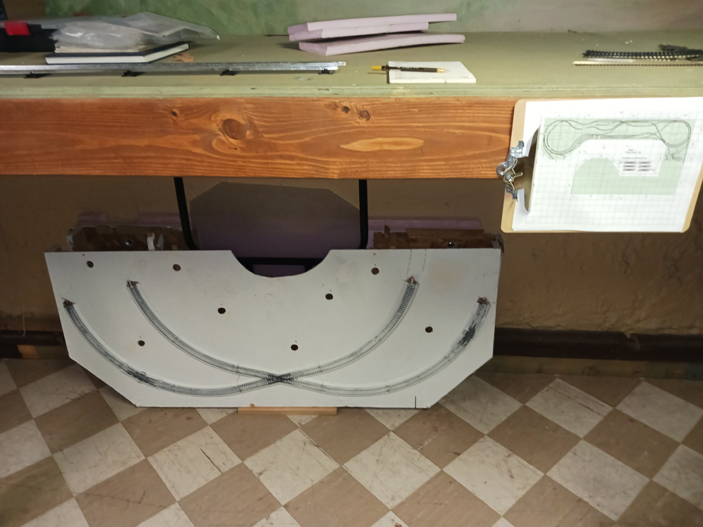
Divorce the octagon module by sawing the OSB in half at the setback with the predetermined saw blade width.
The modules will be reunited after filing edges downward, sanding, painting satin white, and adding suitcase latches. When painted white it has a nice texture for snow. The border could be trimmed with the color(s) of the room or a favorite railroad. Feel free to complete those tasks before proceeding.
Laying track and electrical prep
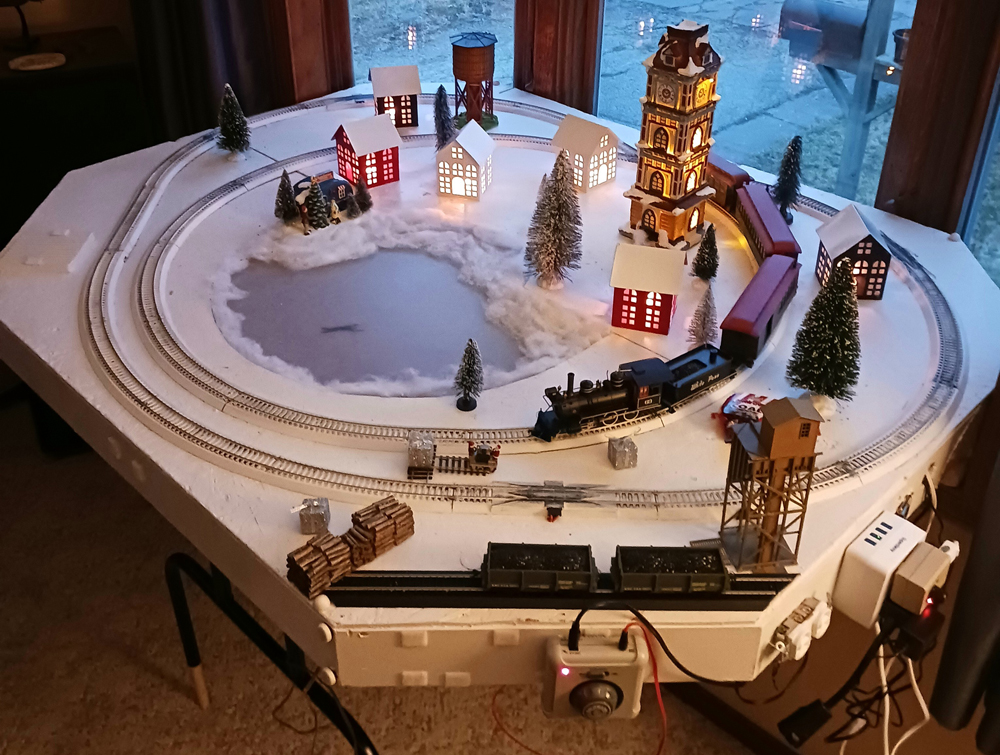
I used black sectional track with roadbed because it’s cheap and is going to be painted anyway. Small track nails were pushed in with a collapsing track laying hand, and do not distort the track or ties. The track plan is designed to span the modules with one full section of track. I then nailed adjoining track sections near the rear only for ease of track assembly. You can drybrush the roadbed with thinned white satin using a wet and dry cloth to clean rail tops as you go.
High voltage electrical requires 1” holes for string C7 lights and the overhead puck fixture. Side exit holes should be 1¼” for 3-prong plugs. Mounting high voltage supply boxes requires screws and key hole slots. An unpowered receptacle was mounted for storing low voltage power supplies. Accessories include a dimmer control, mechanical light timer, and power supplies. The low voltage speaker was mounted on a 4” round hole with ¼” holes for feeder wire. White hook and loop fastener mounts were used for train controllers.
Scenery
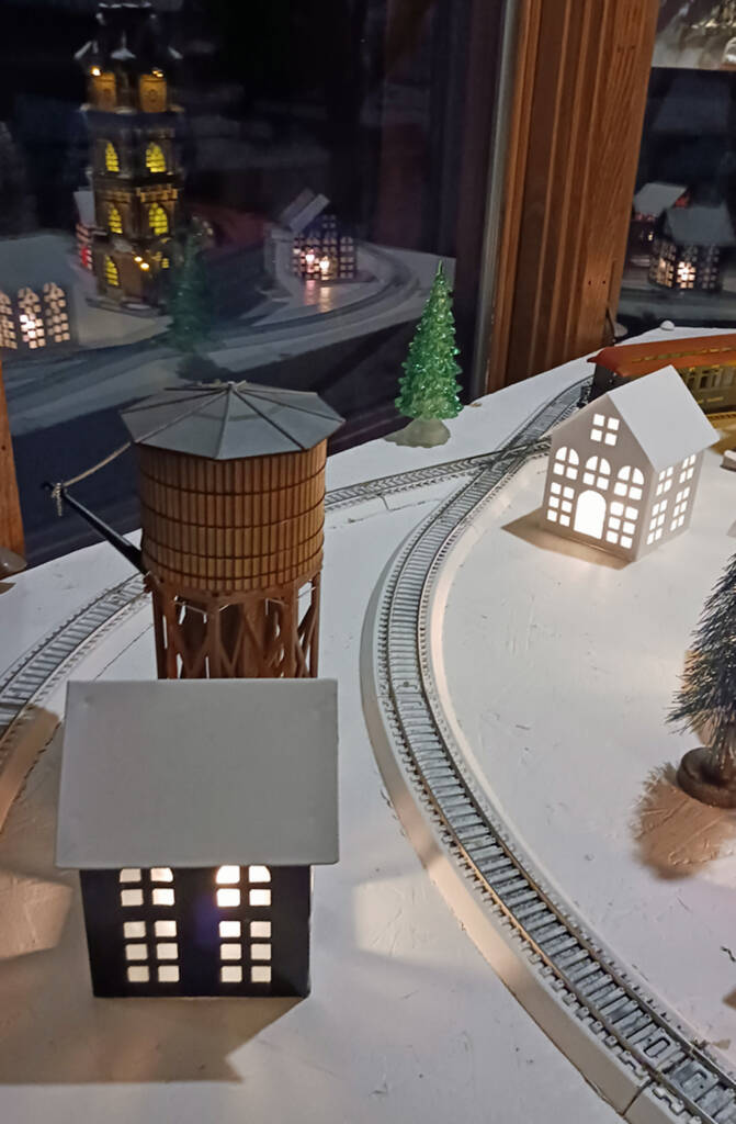
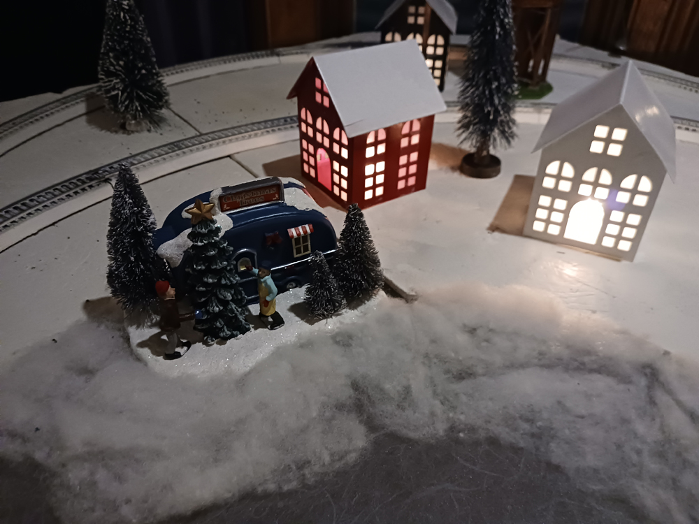
The houses used on the layout were stamped metal holiday décor. They lack a bottom hole for lighting, have no window panes, and have no snow on the roof. I measured the houses, made a drawing, cut it out, put it around the house for a paint mask, and spray painted all of the roofs with satin white. Finally, I used clear tape over the windows to create a frosted pane.
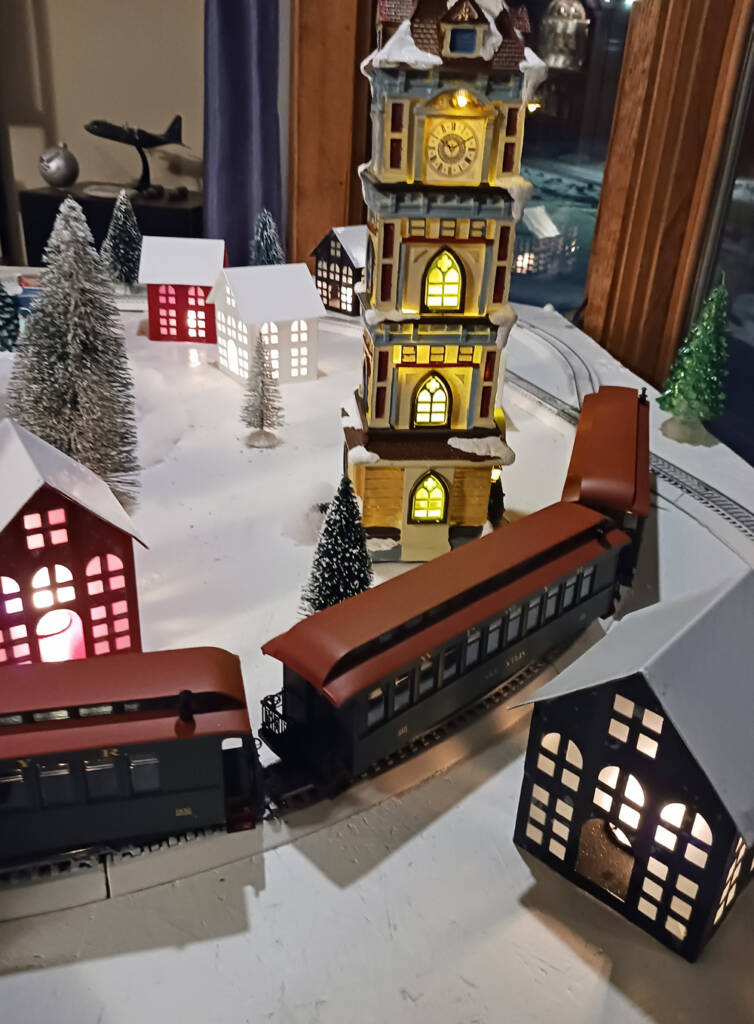
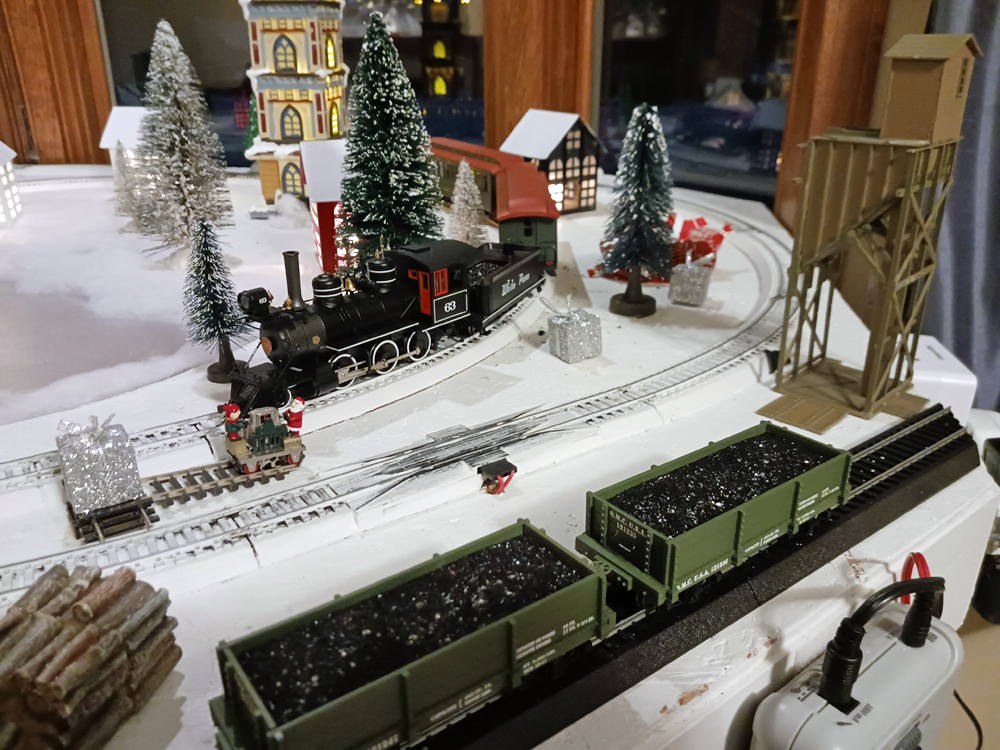
The tower station is lit with light-emitting diodes. The camping trailer, packages, bagged coal, and trees are all off the shelf Christmas décor. The Santa and elf handcar is made by Bachmann as is the sectional track and On3 gondolas. The HO scale water tower was pre-built and the small coal tipple is from Walthers.
Window display conversion
Window preparation
Consider installing roller shades for sun and privacy. Rear loading, close fit, UV resistant shades are preferable. If you are somewhat handy, you can build your own continuous valance to fit. A motorized example provides the best access for year-round operation, privacy, and aesthetics but is expensive. Manual is fine but requires access to mechanical lift cords. If you have spanning draperies, you may be able to close them around the display layout for sun or privacy.
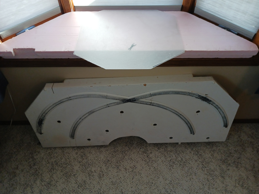
The window base needs to have scratch protection and support the display module. I used foam board cut to fit and thickness for the desired height of the module. Remove and store any operator handles and screens that impair vision or installation. A centered overhead dimmable puck light helps illuminate down on the display. The light was mounted on a L-bracket; it can easily fit behind upper window trim.
The lake
The lake came as an afterthought when the layout became a window display. What do I do with a strange sinkhole in the center of the layout? It’s not visible from the outside but very distracting inside. I did not want to get into complicated techniques, I just wanted to keep things simple. I had some clear acrylic but that would only reveal a carpet lake bottom and table legs. I had used the acrylic to make a seasonal faux stain glass window film insert for privacy in winter when the trees are bare. On one of my trips to my local big box lumber store I found rice paper window film which is perfect for simulating snowy ice on a lake. For humor I used black electrical tape, cut out a small human shape, and stuck it on the back side of the acrylic lake. The depth of the ice is amazing. Some think it is last year’s habitus corpus but I think it is an enthusiastic scuba fisherman. Anyway, the lake is supported on edges sandwiched by lumber and slides in to fit. The topside edges were camouflaged with dacryon artificial snow.
Removable module legs
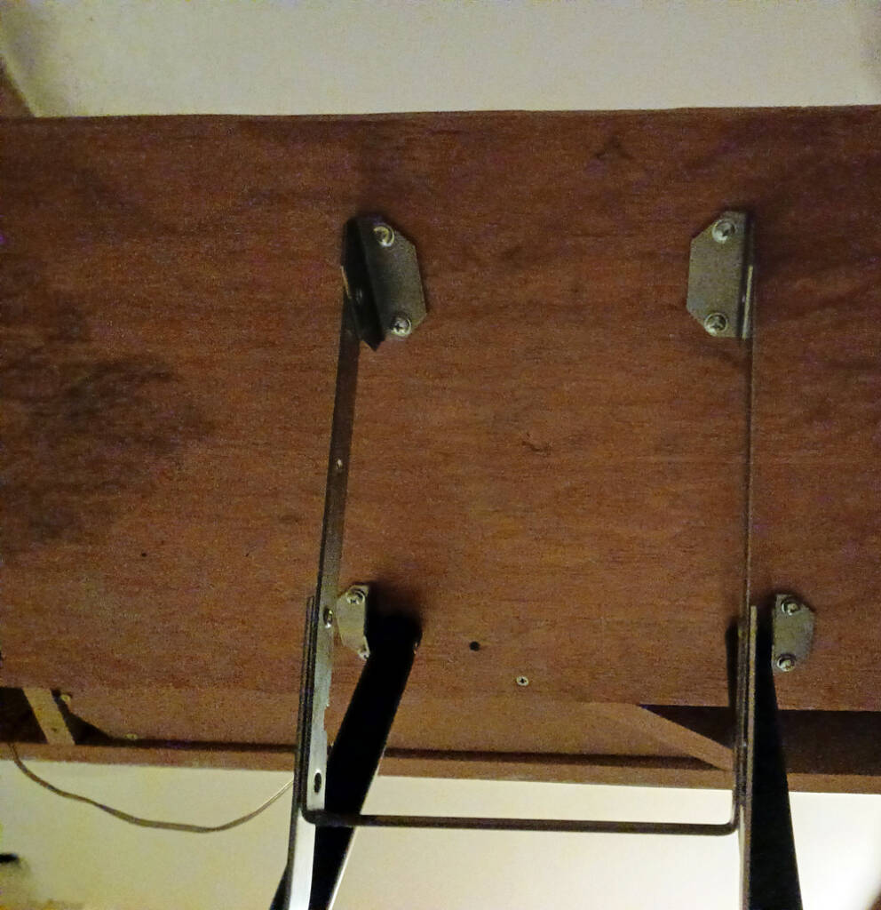
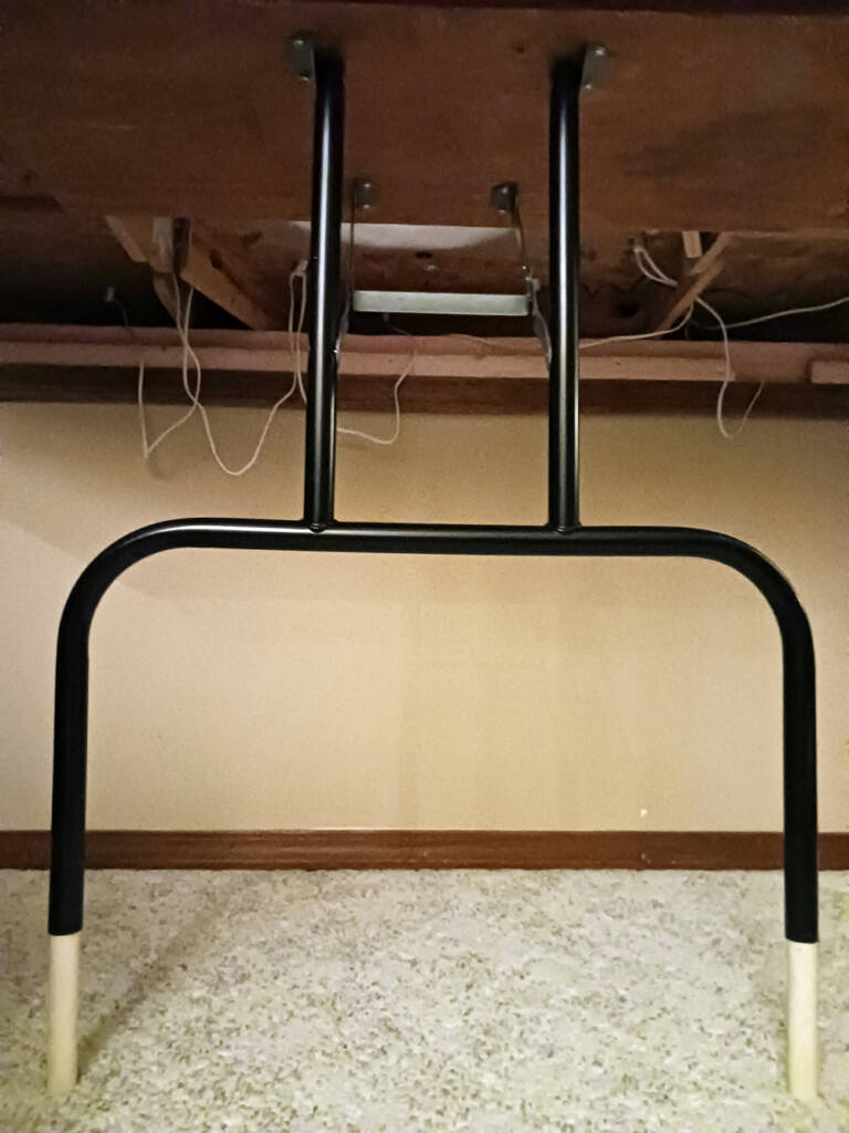
The first year of the display started with wooden saw horse support. Again, that voice haunted me. “Really? You can do better than this.” Another trip to the big box store revealed that the best answer was a banquet table leg. I couldn’t just buy one of course. Underneath the layout is a maze of support lumber with no clear way of leg attachment. A mounting adaptor came to me in the form of a ½” x 14” x 34” plywood scrap piece. I centered the leg on the adapter and attached it. Then I located plywood on supporting members and attached them with 4 wood screws to support members for easy removal. The legs ended up too short for the desired height. ½” plastic PVC plastic pipe fits snugly inside the metal legs. Knowing how deep the pipe goes into the legs, and how much more height is needed, I was able to cut the PVC pipe to the right length. Now they remain sturdy and removable.
