Sketching with Steve
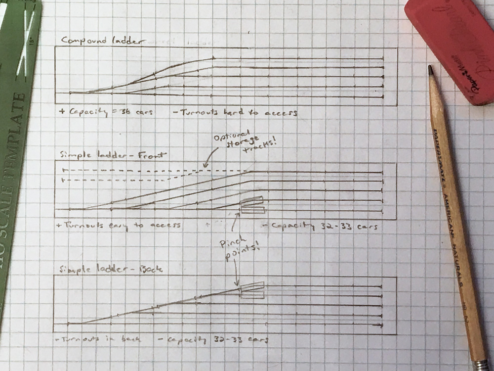
How you arrange the turnouts in your yards may be dictated by the prototype yard you might be modeling and at least in part by the shape of the benchwork at that location. But if you’re designing a yard that isn’t constrained by those factors – say, a staging yard on a nice, straight shelf – there are some factors you might want to consider.
Let’s keep things simple by using just regular turnouts – no fancy double-slips or three-ways. I used no. 4 turnouts in my sketch, because at yard speeds, most rolling stock can handle them. If you’re building a coach or intermodal yard that will regularly handle 80-to-90-foot rolling stock, you can use no. 6 turnouts, but the principles I’ll be illustrating here are the same.
First, we’ll look at simple ladders, where the turnouts all branch in the same direction. The middle and bottom drawings in my sketch are examples of this. This arrangement was favored by the prototype railroads, since a yard worker could line all turnouts from the same side, without having to cross any tracks. This isn’t an issue for us, since we can reach over our cars or use switch motors to line turnouts remotely. If turnout access is an issue, though – say, if you use ground throws to line your turnouts – you should arrange your turnouts in the front, as in the middle drawing.
Both simple ladders yield yards with the same capacity, 32 to 33 40-foot cars, depending on whether cars can clear each other at the pinch points I’ve marked. Both have tracks ranging in length from 5 to 9 cars, making them of varying utility.
You can expand the capacity of either yard by adding a turnout and filling in the empty triangle at the top with another storage track or two, as shown in the middle drawing. However, its switchback access makes it awkward to switch, especially in a hidden yard, and reduces the utility of the switchback track.
Compare these to the top sketch. In a compound ladder, turnouts branch from both sides of the initial turnout. This saves space; even in this short example, it gains three or four cars in capacity. What’s more, the legs are of more uniform length – two of six cars, three of eight. It’s difficult to reach the turnouts in the middle of the yard, but if you control them with switch motors or fascia-mounted knobs, that won’t be a problem.
Consider a compound ladder to increase the capacity of your staging yard.




When designing a compound ladder yard, and with Caboose Industries ground throws (GT), you can still place the GT outside the yard area by using a brass throwout rod inside a brass tube. You will need to drill a hole in the GT bar (I cut off the pin and then drill a hole the diameter of the rod for a slip fit). The other end of the rod can connect to either the “normal” hole on the throwout bar or under the track to a drilled out center hole between the points.
These work well and are easily installed in a groove cut into the roadbed (It does not show after ballasting). Be sure the tube is slightly shorter than the length of the points throw and is [reasonably] parallel with the throwout bar.
I have several at needed locations around my layout, not just in the yard areas, but also in tight switching areas where the real estate is at a high premium.
IMO, of course. ?
Drawing 1 and 3 have one drawback. If using hand throws like Caboose Industries ground throws some of the turnouts can be blocked by cars in front. If you run the ladder from back to front not front to back you do not have the problem of ground throws being blocked.