The basic idea behind the DCC- friendly concept is to reduce the potential for short circuits to occur. One thing to keep in mind is that you can usually convert a DC-powered layout to DCC without going back and modifying all of the track and turnouts. However, addressing some of the topics covered in the following paragraphs may make things easier in the long run, especially if you are building a new layout. In this article I’ll cover various things I did to make the installation of the gantlet track as DCC friendly as possible. For more information on DCC-friendly practices, see Allan Gartner’s “Wiring for DCC” website (www.wiringfordcc.com).
I’ve redrawn an illustration from my March 1998 column showing what a DCC-friendly turnout should incorporate. See fig. 1. Several years ago I bought a collection that included old Shinohara turnouts, which definitely weren’t DCC friendly [new HO scale code 83 Walthers Shinohara turnouts are offered in a DCC-friendly design. – Ed.] I converted them for use on my DCC layout using a multi-step process: I isolated the frogs, powered the frogs using a mechanism to switch polarity, reinstalled the point rails so they’re powered independently, and tied the closure and point rails electrically to the stock rails.
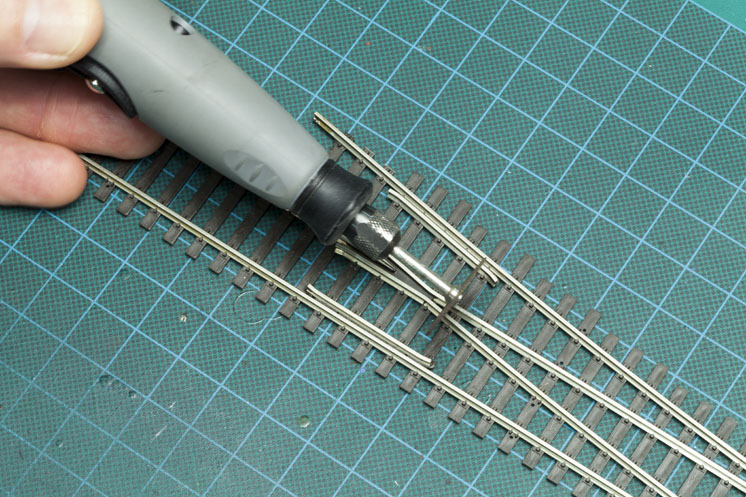
I isolated all the frogs by cutting through the rails on each side using a motor tool with a cutoff disc, as shown in fig. 2. To prevent any short circuits from occurring at these gaps due to rail expansion or movement, I glued a small black styrene shim in each opening and trimmed it to match the rail profile, as seen in fig. 3. After I painted the rails, the shims were barely noticeable.
In the leads to my gantlet track are two turnouts on the southbound main, which lead to two short sections of track left over from the old bridge approaches. I included them to allow the track crew to move in a heavy crane for removing the old bridge, adding interest to the scene.
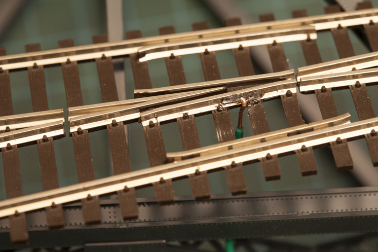
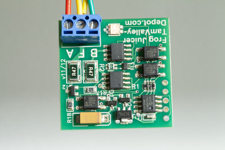
I line the turnouts with Caboose Industries ground throws with no auxiliary contacts to switch polarity. I wired the isolated frogs in these turnouts using a feeder wire soldered to the side of the frogs away from the aisle where it wouldn’t be seen. See fig. 4. I connected them both to a Tam Valley Depot Mono Frog Juicer
(no. MFJ003U) to control polarity.
To prevent shorts in the gantlet track frogs, I isolated them the same way and powered them using another Mono Frog Juicer, as seen in fig. 5. I was able to use a Mono Frog Juicer for each pair of frogs because they always need to be the same polarity, since either a northbound or southbound train will be using the pair of them at the same time. A wire from each frog in the pair connected to the Mono Frog Juicer ensures they both are the same polarity and change automatically as trains pass through the gantlet track – inexpensive, no shorts, and very DCC friendly.
Fixing the point rails
The point rails on old Shinohara turnouts are electrically connected through solder joints to metal strips at the switch rod and where they meet the closure rails. This results in one point rail always being the opposite polarity of the adjacent stock rail when it’s in the open position. If a metal wheel should derail in the turnout, it could easily touch both of these rails, creating a short and shutting down your booster. It can also lead to damage if the booster is slow to, or fails to, shut down.
The closure rails are electrically connected to the frog, so they’re the same polarity, as well. Electrical connections are made where the point rails contact the stock rails and through a metal strip under the point rails and closure rails.
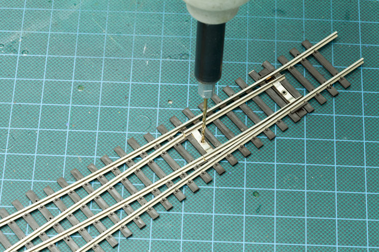
All of these connections depend on a tight physical contact that often works loose or is interrupted by dirt, grease, paint, and scenery glue. To make them reliable and DCC friendly, I drilled out the rivets holding the point rails in place (fig. 6) and measured the distance between them at the point ends.
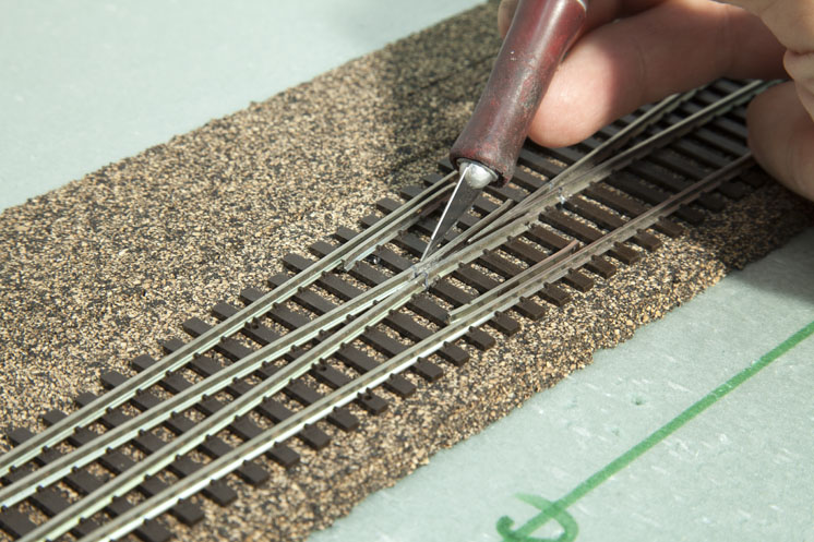
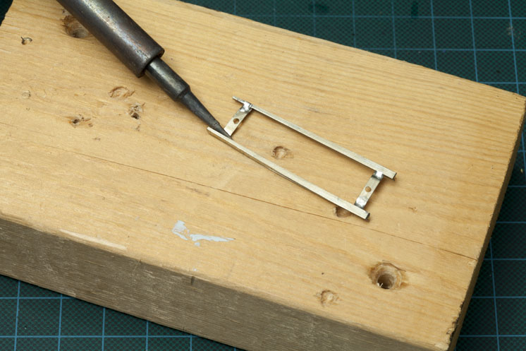
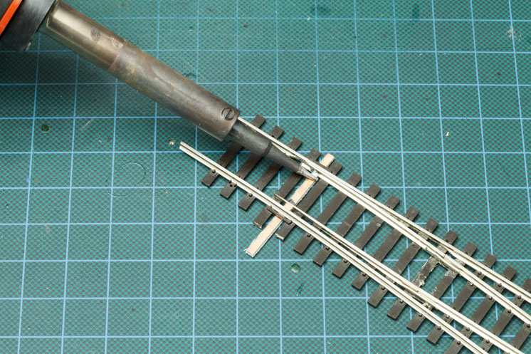
Using a soldering iron, I disconnected the point rails from the metal strips that hold them together. See fig. 7. I then used needlenose pliers to pull the metal strips from under the ends of the closure rails and used a sharp no. 11 blade to cut off the plastic support.
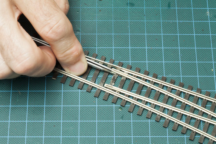
I slid rail joiners onto the ends of the closure rails. It may be necessary to slide a no. 17 blade under the ends of the closure rails to make room for the rail joiners to move into place. Then I slipped the point rails into the open end of each rail joiner. This can be seen in fig. 8. The fit should be tight enough to firmly hold the point rails in gauge yet still allow their ends to move about 1⁄8″ to each side. A pair of needlenose pliers are useful for tightening the rail joiners.
Next, I cut a new switch rod from Clover House copper clad printed-circuit-board tie strips, and slid the new switch rod into the opening underneath the points. I then soldered each point rail to the copper using the measurements I’d made of the old points. See fig. 9.
Finally, I filed a notch through the copper surface in the middle to electrically isolate the two point rails.
Powering the rails
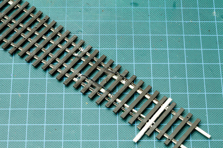
At this time, the point rails and closure rails were connected and electrically independent but still depended on the physical contact with the stock rails for power. To remedy this, I soldered short jumper wires between the stock rails and closure rails on each side of the turnout, then ran a short jumper wire between each closure rail and the point rail attached to it, as seen in fig. 10. This guaranteed that the point and closure rails would always be the same polarity as their respective stock rails, lessening the chance of shorts, and would never have to depend on physical contacts for power in the turnout.
Just because a turnout is old doesn’t mean it can’t be made DCC-friendly. Using these easy-to-follow techniques, you can eliminate the potential for short circuits and keep trains moving without interruption.








I have installed a bunch of Shinohara turnouts that are NOT DCC friendly a d they work just fine with a few minor modifications:
1) you must remove the brass wiper from under the point rails. I use a dental pick to turn it 90 degrees then flex and stress crack it while holding the point rails down
2) all of the metal wheels are in gauge such the the flanges fit loosely in the track gauge with maximum “play” back and forth when in the gauge. If it is tight it is not right. Believe me, this is VERY important
3) I paint the inside edge of the point rails, next to the stock rails with clear fingernail polish. This acts as an insulator for any errant wheeler that is out of gauge. The polish fries in 15 minutes, then you paint the other point rail. Not the top of the rail, just where it would touch the stock rail when closed. Works great. I also always power the frog from the switch machine.
I’d love to see a simulation of these trains having a go on the tracks! I much prefer enjoying the different layouts thateverybody is constructing rather than getting into it myself. I reckon that I’d want to perfect it too much and it’ll end up being an ever-expanding project!
How do the turnouts sit level on the roadbed with the jumpers (fig. 10) under the ties?