Soldered feeders make it easy to wire a layout because they can literally be installed at any time in any location. All you need to do is drill a hole through the roadbed next to the rail to bring the wire up from below.
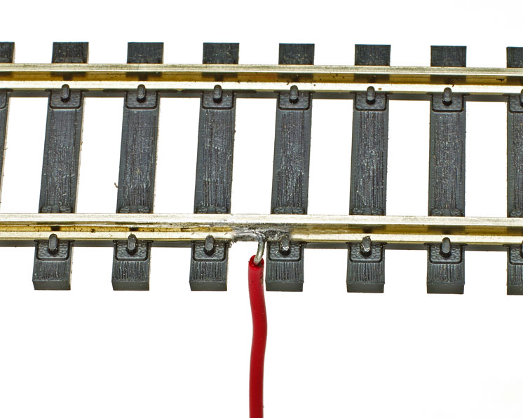
I squeeze the trigger to heat the soldering tip before I bring it into contact with the rail and wire. As soon as the solder flows into the joint, I remove the heat to keep from damaging the ties. Avoid applying too much solder, as it looks sloppy. An aluminum soldering tool comes in handy to hold the soldered wire tight against the rail for the few seconds it takes for the joint to cool.
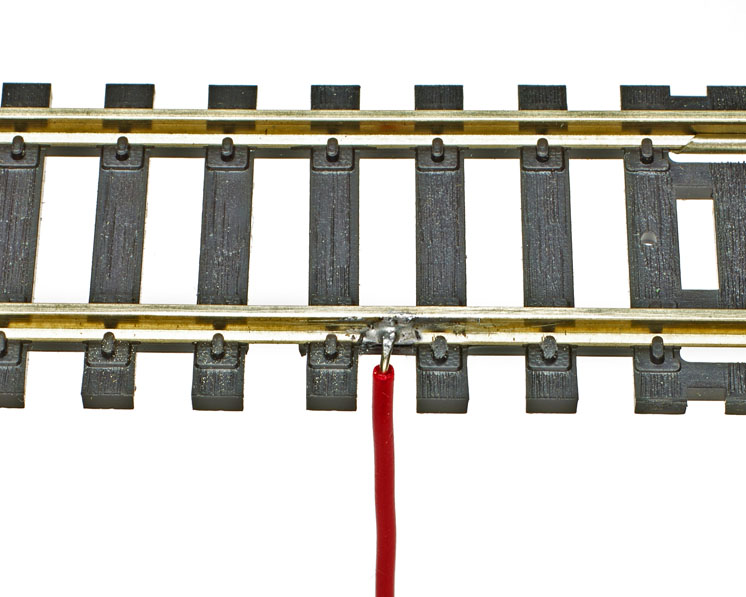
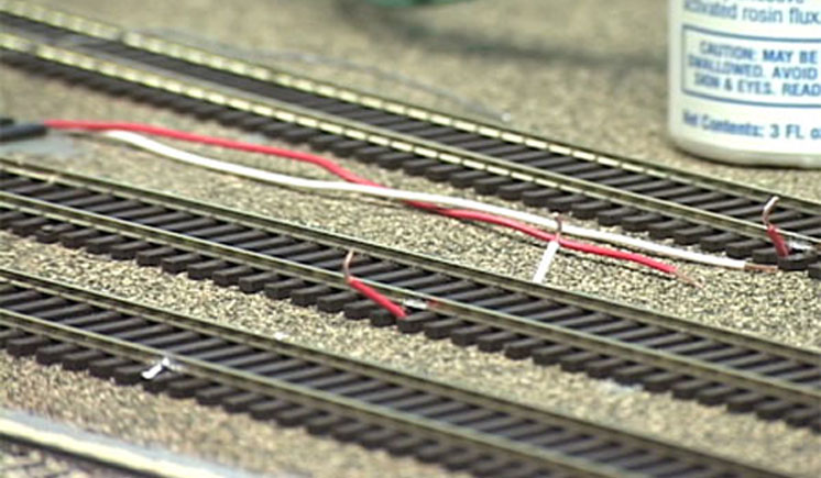
Modelers who lay their own track may flatten and shape the end of a feeder wire to look like a spike head. Figure 2 shows this technique out in the open for visibility. In practice, the wire should be concealed by passing it down through a hole in a wood tie before it’s soldered to the rail so the feeder blends in.
If the track has plastic ties, I protect them from the heat with wads of wet paper toweling that I pack around the soldering location on both sides and behind the rail. A couple of three-point metal track gauges can also help dissipate the heat.
Some modelers like to use a pencil- type iron for this, but if the iron takes too long to heat the rail, the built-up heat can distort the plastic ties. In a similar manner, the proximity of high heat from a large soldering iron or gun may also cause the tie ends to melt.
Camouflaging the connections. If you’re careful and have the right combination of rail height and flange depth, you can solder feeders to the inside of the rail, but this requires great care to avoid difficulty with the flanges.
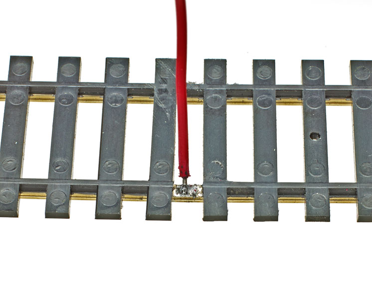
Some modelers attach feeders to the underside of the rail so they’ll be hidden from view, as shown in fig. 3. This takes additional planning, because holes must be drilled through the roadbed directly under each feeder wire’s location before the rail can be installed.
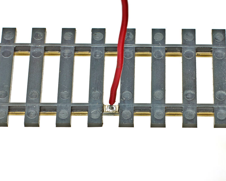
Some model railroaders like to drill a wire-sized hole into the base and web of the rail so they can solder the end of the feeder wire into the hole. See fig. 4. The one drawback to both of these methods is the limited access to the power feeder if the soldered connection ever breaks down.
After the track feeder connections have been soldered, I splice these light wires into the heavier no. 14 wire I use for long runs throughout my layout.
No matter which method you use for soldered power feeders, be careful to test each one before adding any paint or ballast. Lightly airbrushing the track and ties with a rusty, brownish-black color will hide any soldered joints and feeders.