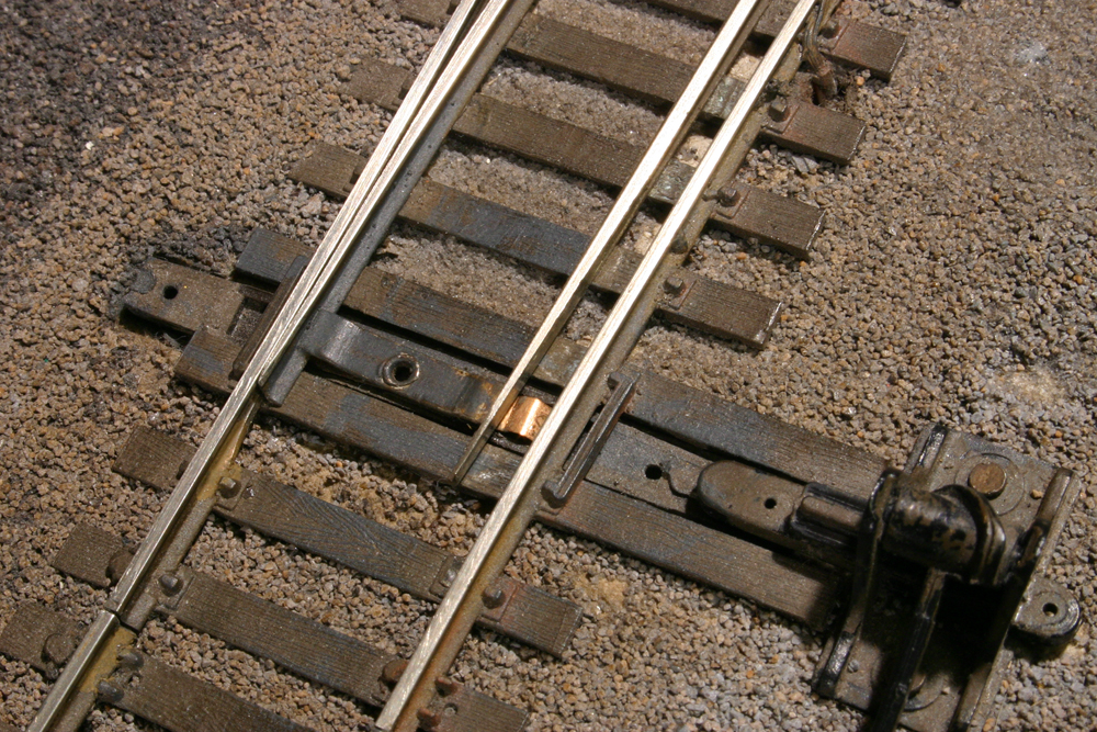
Some power-routing turnouts use thin metal tabs to provide contact between the stock rails and switch points. These tabs are often unreliable, especially on older turnouts, and can cause locomotives to stall.
Tune-up tips for power-routing turnouts
Power losses and short circuits don’t have to be a chronic problem when using power-routing turnouts. By taking a little extra time when wiring and installing your turnouts, you can avoid operating headaches later.
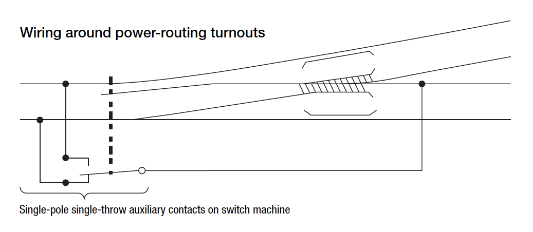
Instead of relying on contact between the point and stock rails, you can use the auxiliary contacts on a switch machine to more reliably route power, as shown in the accompanying illustration. These contacts act as relays that change when the turnout changes, sending power to their corresponding frog rail. When using this arrangement, you’ll need to make sure that there isn’t excessive play in the turnout’s mechanical linkage. A short circuit can occur if one of the auxiliary contacts closes before the opposite switch point opens.
A short can happen at an open switch point in another way. If the open point and its adjacent stock rail are of opposite polarity, and the gap between them is too narrow or a metal wheelset is out of gauge, the wheel will bridge the gap and cause a short circuit. Most commercial turnouts follow the National Model Railroad Association standard in having points open un-prototypically wide to minimize the potential for a short.
I avoid this problem by wiring each point rail to its adjacent stock rail so that they have the same polarity. In this case, the points can’t be connected by a metal bridle bar; they must be insulated from each other.
First, I isolate the point rails from the frog by gapping the rails on both ends of the frog. Then I attach jumpers from each point rail to its adjacent stock rail. This arrangement allows me to build turnouts with a narrower, more prototypical-looking gap between the open switch point and stock rail.
Short circuits can also occur where rails are gapped instead of joined with a plastic joiner to insulate them. I cut a narrow gap where I want to insulate a rail because I think the gap looks less obvious than a plastic joiner. But the two rail ends can creep back together with the contraction of wood benchwork due to humidity changes, causing a short circuit. To avoid this I put a sliver of gray plastic into the gap, which is barely detectable from the rest of the rail.






I am fairly new to model railroading. I am currently building a layout and have run into an electrical problem. I have electrical connections to the rails around every four feet or so. There are three major turnouts from the main line that when any of the three are individually activated, the locomotive immediately loses power(while still on the main track). Two are very short sidings with no electrical connections yet. No visible sign of anything causing a short.
goodmornin’, referencing the “Theo Cobb illustration”, in it’s current configuration, would that not be a dead-short if the out-going leg was powered (joooost curious) ? (i know enough to be truly dangerous).
A thought here pursuant to turnout control; using an actuator linkage system with a slide switch (Linn Westcott in MR) opens up a whole spectrum of electrical control. If you can find the back issue, that would be helpful.
Also, there is a great deal about this subject on ‘You Tube’; the one I liked is using servos, with or without Arduino controls (pertinent articles have also occurred in MR). I secure the servo to a piece of PC board, then line up a SPDT momentary switch, and install the whole under said turnout. Using small relays or contactors, this can be used to control track, signaling, etc. Pretty much any turnout can be adapted to this system. And it is also pretty inexpensive.