My N scale model railroad has about 50 mainline and storage track turnouts, all controlled by Tortoise by Circuitron motors and Digitrax SE8s for total control via Java Model Railroad Interface (JMRI) as well as manual local and via Digital Command Control with a DCC throttle.
I’m adding another 30 to 40 or more turnouts for yard tracks and sidings. The cost for automation was too high, both in dollars and hours spent under the layout. I needed a simpler solution, such as N scale manual turnout control.
A plan comes together
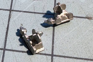
My mainline turnouts are all from Micro Engineering, which use a spring to keep the points in place. I planned to bend my own springs for the Atlas turnouts I’m using on the new installations. I didn’t want operators pushing on the point rails as they can be delicate, so I needed an actuator or handle to move the points through the switch rod. I found an interesting candidate for a handle in the extra parts that come with each Micro Engineering turnout. Micro Engineering includes a “scale” cast metal ground throw switch stand. I couldn’t use them on the mainline turnouts due to the motor control, but I thought they’d make great handles that look like ground throws. The stands are available separately from Micro Engineering.
Close but not quite
Unfortunately, many of our simple ideas don’t pan out. I found it near impossible to form the proper spring shape, install it on the turnouts, and have it function as desired.
A friend, Chris Shulte, stopped by to check on the progress of my railroad build and we got into a discussion about my idea and attempt to create a manual turnout control for the yard using the spring method as the locking mechanism. His thought was something much simpler: “We just need some form of interference between the switch rod and the roadbed to hold the points in place.” And not too much interference would be needed as it is N scale after all. He tossed around a couple ideas, and eventually a solution was found: a Micro Engineering switch stand handle and a simple piece of styrene to hold the points in place with friction.
Preparing the parts
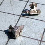
The build is straightforward. Start by cleaning up the switch stand castings, especially the flash from the bottom surface of the switch stands, using a knife and sandpaper. The bottom needs to be flat and smooth so it can slide on the headblock ties.
The castings are quite small, and the non-functioning throwing lever is particularly fragile and can be easily broken off. Be careful handling at all times to avoid bending/breaking them as once broken they really can’t be repaired sufficiently and hold up to the intended use.
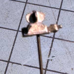
Next, drill a hole in the bottom of the casting, trying to center it but keeping in the thickest part of the casting. The hole needs to be about the diameter of the wire that will reinforce the connection between the switch stand and switch rod. I tried not to go through the top of the casting, but once the wire is installed and the stand is painted it’s not noticeable. Clean the castings in alcohol to remove dust and oils. Once the parts are thoroughly dry insert a small piece of the piano wire into the hole and if it fits, secure it with a drop of cyanoacrylate adhesive (CA).
I primed and painted the assemblies with gray Tamiya Fine Surface Primer L, then black enamel, both from a spray can, then brush-painted the targets red and green with dollar store paint. Once dry (overnight) I sealed the switch stands with several light applications of Testor’s Dullcote.
Once thoroughly dry, cut the piano wire to length. It should protrude from the stand no more than the thickness of the turnout switch rod (about .040”) to prevent it from getting caught on the roadbed. A completed switch stand is shown.
Installing the switch stands
On to the turnout. I assembled the switch stands for my N scale manual turnout control with the turnouts installed on the railroad. It’s easy to damage the assembly during installation of the turnout. And, the turnouts need to be installed to apply the styrene strip. I took photos with the turnouts off the layout for clarity.
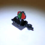
Determine what side of the turnout the switch stand will be mounted. Typically a switch stand is on the main line side of the turnout, but it could be either, depending on how you will access and close/throw the turnout. [Railroads attempt to limit the number of times a crew must cross the tracks to line a switch – Ed.]
Remove the two headblock ties on either side of the switch rod. You could leave these two ties in place, but there’s too much side-to-side play on the Atlas turnouts for my liking. On my layout I also remove the ties from the opposite side and shorten the switch rod there, too.
Locate the position for the hole in the switch rod to accept the switch stand wire. I find that approximately .009” (.225mm) from the end of the turnout ties with the points in the thrown position is a good location for my application. The position is important. If the hole is too close to the turnout, the switch stand might interfere with the trains, especially when the switch is thrown.
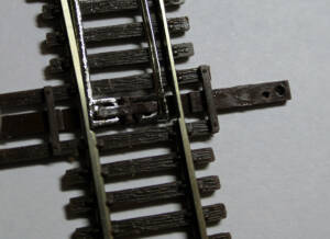
Be careful drilling the hole as the plastic is very slick and the drill bit can wander. Roughing up with sandpaper or making a drill-starter point with a pushpin can help prevent that. Again, the hole should provide a snug fit to the piano wire.
Next, cut down the switch rod to remove the portion with the original hole and shorten it, leaving sufficient surface to support the full base of the switch stand.
Glue the painted switch stand in place with Walthers Goo. Prepare the switch rod by roughing up the top surface where the switch stand will be placed with sandpaper to provide a good gluing surface.
Then place a small amount of Goo around on the top surface of the switch rod around the hole and on the bottom of the switch stand casting. Use a toothpick or similar applicator, being careful not to apply too much glue or get any on the roadbed. . Allow to dry overnight.
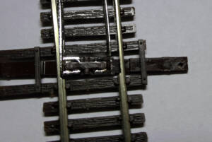
Next, cut the styrene strip to size that will be placed under the switch rod. A piece of strip styrene about 4mm x 10-15mm and .15mm thick worked well for me. You may find a longer/shorter or thicker/thinner piece is needed depending on how securely you mount the turnout to the roadbed and how tight you want the points held. I found both .10mm and .15mm (.005” to .010”) worked well with my turnouts. Only a small amount of interference is needed to hold the points securely. Don’t overdo it. You don’t want to exert too much force on the switch stand to line the turnout. Insert the styrene under the switch rod and position it so it’s completely under/between the rails and doesn’t protrude from the rails. Test and adjust accordingly. When it’s the right size, remove the strip and color using a black permanent marker to camouflage it. Then reinstall the strip under the switch rod. Do NOT glue this strip in place. Leave it in place, held by the interference between roadbed and switch rod so it can be removed or replaced later if you desire. It will stay in place with just the pressure provided by the turnout to the roadbed.
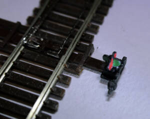
Once the Goo on the switch stand has dried for 24 hours, confirm the points can travel through their full range of motion. Also check that the styrene strip can’t be seen when the switch is thrown in both directions. The styrene strip shouldn’t be under where the switch stand will be located.
Here come the headblocks
Now we’ll turn our attention to the headblocks that will support the switch stand and switch rod. The Micro Engineering turnouts have molded headblock ties in the shape of a “U”. If you can’t obtain the same headblocks, fabricating them out of spare ties is simple to do and yields the same result. As the headblocks are a bit too long visually as well as physically in tight areas (like the yard) I trimmed them to size. I found an 11.5mm length worked best and allows the switch rod to move freely through its range of motion without it touching the end of the switch rod or limiting the length of throw.
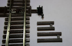
Slide the headblocks in place around the switch rod, under the switch stand, and position it so the side ties are in line with the turnout ties. Then glue in place using a small drop of cyanoacrylate adhesive (CA) on a toothpick, applied on each side of the headblock ties placing the glue on the outside the ties, away from the switch rod. Make sure no glue gets on the switch rod. Allow all the glued components to cure fully. Note the switch stand is removed for clarity on the placement of the headblock ties.
That’s it. You now have a “scale” ground throw for your turnouts that works and looks great. Only a small amount of pressure on the switch stand should be needed to line the switch, and the points will stay tight to the stock rails until it’s lined in the opposite direction.
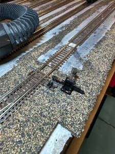
Here is the end result along with a comparison photo of an N scale sprung ground throw next to a completed switch stand control. Give this method of N scale manual turnout control a try!
Materials list:
80-302 Micro Engineering N scale switch stand
Headblock ties
.020” diameter piano or other hard wire
Drill bit to match diameter of piano wire (with a snug fit)
Strip styrene, .010”, .015”, .020” or similar


