How To Arduino source code for a model railroad signal system

Arduino source code for a model railroad signal system

By Angela Cotey | October 25, 2016

| Last updated on May 27, 2022

Online bonus from Detlef Kurpanek's article in the December 2016 Model Railroader

Email Newsletter

Get the newest photos, videos, stories, and more from Trains.com brands. Sign-up for email today!

Arduinosourcecode
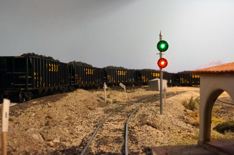
Get the source code for Detlef Kurpanek’s Arduino-controlled model train signal system described in the December 2016 Model Railroader.
In the December 2016 Model Railroader, Detlef Kurpanek describes how designed an operating model railroad signal system that uses Arduino microcontrollers. As an online bonus, you can download Detlef’s source code for the project by clicking on the link below.

5 thoughts on “Arduino source code for a model railroad signal system

  1. Just came across the article and was looking forward to downloading the arduino sketch, but to my disappointment I see it is a PDF file, which is useless. The code needs to be the .ino Arduino sketch or at a minimum a plain text file to maintain line endings.

  2. I’m getting into Arduino also and see great uses for flahing lights on towers, crossing signals, and loads of other applications. MR Mag could almost start a column devoted just to Arduino stuff.

  3. I’m coming to this discussion a little late, but there were a couple of other items in the article that should be corrected. First, the author states “…several analog outputs … drive servo motors…”.

    There are no analog outputs, they’re all inputs. Six of the digital pins can generate pulse width modulation outputs (PWM) which could be thought of as pseudo-analog, but they’re not the same as the analog pins. In any case, you don’t drive servos with analog outputs, they are controlled by a digital signal whose duration varies, in most cases, from 1000us to 2000us. The duration of the pulse defines the servo position.

    The author also says”outputs are limited to 40ma”. That is correct, although a max of 20ma is suggested for safety. However, there is an overall limit of 200-400ma, 200 to be safe. So you can’t have all the pins high at the same time.

    Finally, the article says a Uno can take power “from 5 to 24” volts. The Arduino specs say the limits are 6 and 20 volts, with 7-12 recommended. The voltage regulator gets quite hot at 20 volts. I run mine with 9 volt regulated wall warts.

  4. I fully agree with Robin Simonds comment and want to add my 50 cents. Using the information on the web I was able to build a small CTC prototype using the Arduino UNO, some shift registers, and some ideas about and plans of block detection with current sensors or IR-gates. I build on top of what I have learned there on my – small, but great – model railroad where I will use this for my small hidden staging yard.

    Most useful ideas I got from:
    * the original Bruce Chubb article with his Visual Basic Code way back in MR (late 80’s, 90’s ?). Transforming is ideas into C/C++ (Arduino) was not very difficult.
    * Nick Gammon in his Gammon Forum (google for “Gammon” and “Arduino Shift register”).
    * a Canadian site that shows how to current sense and transform that signal into both open collector and bipolar outputs using a simple 555 (genious!) – google for “Block Occupancy Detector For DCC” and “http://home.cogeco.ca”. This site has a myriad of ideas! I was able to adapt the same principle with an IR-detection circuit. Thank you Mr. Paysley (if that is your name).
    * Debouncing is best NOT done in the Arduino-code. Google for “debouncing switches” and you will find some very simple circuits that clean up the signal for good (switches, toggles, good old fulgurex TU-motors).
    * And don’t forget the guys at Iowa Scaled, the give away for free great ideas about a MR-Bus protocol that is simply – wow!

    The electronics bug has bitten me just 4 years ago, before that I was simply too afarid that I would not understand more advanced (for me) things like BJT or MOSfets and such. Believe me, it is easy, and with a bit of interest and learning from your failures (and successes!) you wil make big improvements. And it is fun!

    As a MR subscriber for many years (and before that avid reader since the mid 80’s) I see the decline of craftmanship and DIY. Even MR – sadly! – reflects that tendency as the number of pages is in steady decline since the early 2000s. I know, it’s easier to download an app and “play” with it, and the next and next. You want to fly an RC controled plane? You may do so virtually, or you buy a supercheap plastics model – screw around with it a bit – and then dump it.
    Same tendency with model railroading, so it seems to me. Just consuming will not enhance our hobby, nor any other, that is. Yes, I enjoy and am greatful for the super detailled models on can buy nowadays off the shelf. But, hey, how much fun I have building one of those shake the box kits, enhance them with better grab irons and such, and then paint and weather them. This one then is special for me, because .. “it’s my baby”. I think you know what I want to say. And it’s the same when you just “screw around” with a bit of electronics, not only consume.

    So, Thank you Detlef Kurpanek for your article, thank you @ MR-staff for publishing it. Keep on, give us more of that hands on stuff. Our hobby needs that 🙂

  5. I am delighted so see another MRR article exploring the potential of Arduino microcontrollers in Model Railroading. My hat is off to you folks for recognizing and responding to a little-known trend in the hobby. I have been working with and blogging about Arduino technologies in N scale model railroading for several years now on thenscaler.com. I noticed a couple of issues in the article that could be misleading for readers who are not familiar with the Arduino platform.

    First, the article inaccurately states and illustrates (Fig 1) that the UNO, a very commonly used board, has “13 digital Input/Output points.” As the illustration shows there are two banks of “I/O points”–commonly referred to as “pins” within the Arduino community. One bank consists of 14 (not 13) digital pins numbered 0 – 13. The other bank contains 6 Analog Input pins, so called because these pins can be read by the on-board Analog-to-Digital converter. However, aside from that special capability, all 6 pins can be used as basic digital (non-PWM) pins. So an UNO can furnish a maximum of 20 basic digital pins.

    The author’s choice to go with a MEGA is understandable because of the sheer number of pins the MEGA offers. Because there was no discussion of the ways you can inexpensively multiply Arduino inputs and outputs (again, understandable given the limitations of MRR), some readers might be misled into believing that pin count is the primary criteria for board selection, and when they run out of pins they are out of luck.

    In fact, there are inexpensive and easy-to-work-with components that will multiply the I/O capabilities of any board. For example, an inexpensive digital logic/output chip know as a Shift Register (readily available in hobbyist-friendly DIP format) can supply 8 digital outputs that cost only 3 pins on the Arduino board. Further, Shift Registers are serial devices (technically, serial input, parallel output) that can be connected together to form a chain of digital outputs, all controlled by just 3 pins. I calculate that an UNO could easily handle 800 digital outputs on a chain of 100 shift registers, at a resource cost of the three pins and 100 bytes of memory. A MEGA with 4 times the memory resources of an UNO, could support thousands of shift register digital outputs.

    Further, using Shift Registers for basic digital outputs helps solve three problems that that author identified and had to solve. First, because each shift register is individually powered, they put no power load on the Arduino beyond low current signalling. Thus, your power issues are simplified and you only need to worry about total power consumption and power supply load.

    Two other power problems identified by the author — current per output pin limits, and the problem of mixing common anode / common cathode devices — can be easily solved using a Shift Register chain and adding Darlington Drivers when needed. Darlington Drivers (also available in DIP format) are current-sinking switching devices that can be controlled by the outputs of a Shift Register. Darlington Drivers allow the Shift Register to handle common anode devices and, because they are current sinks, can switch up to 500 mA per channel and handle inductive loads (motors, for example). Finally, the circuit a Darlington Driver switches need not be at the same voltage as the +5v Arduino logic; voltage on the switched circuit is independent and can be higher (up to the limit of the chip) or lower than 5 volts. So long as you tie all grounds together, it works flawlessly.

    Two 50 cent chips and very simple, well-documented circuits can solve the common sorts of problems that the author encountered. That said, I offer my congratulations on a successful and interesting project. I hope to see a lot more of this in the future.

    I want to encourage those who find this subject interesting, but don’t know where to start, to thoroughly explore the Arduino.cc website — especially the reference materials and the “Playground” where interesting ideas are explored and many common problems solved.

You must login to submit a comment