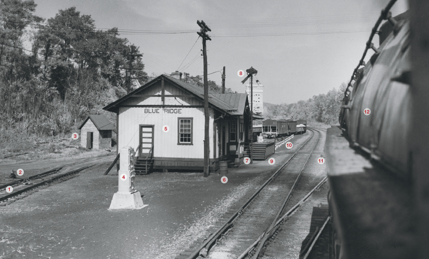
1 Split-point derail device. Considered more effective than a lifting-block derail when there is extra risk of cars rolling out onto the main line from a “house track” or “back track” (terms for station trackage other than a passing siding), or from an industry track, especially when there is a descending grade toward the switch, as is the case here. These are industry tracks, and the stone cars from the crushed stone tipple they serve, seen beyond the station, would be considered an extra risk because the loading method would be to let empties move under the tipple by gravity and then toward our vantage point by gravity when loaded, restrained by handbrakes. When open, the point directs the wheel of a car onto the ties.
2 Switch stand for second industry track. This is called a ground-throw switch stand as opposed to the high-banner switch stands used for main-track switches; the latter are intended to make the switch position visible from a greater distance.
3 Outhouse. No toilet facilities are provided inside the station building. Many railroad stations were remote from sewer lines, and the expense of a septic-tank system would have been considered excessive. Brick construction is unusual for an outhouse; perhaps there was some secondhand brick readily available.
4 Instrument cases. These house the relays and batteries for the control of the power switches on the crossover that the engine is just passing. The crossover is set up as trailing- point for the normal direction of traffic. This was the usual practice for crossovers on double track, to prevent a wheel from “picking a point” and derailing a car or locomotive onto the other main, but in this case the crossover has its points locked by the switch machines and could have been made facing-point. However, this is a location where helper engines that had cut off the rear of eastbound trains at this summit station would cross over to the opposite main to return to the base of the hill, so for them, this is a facing- point move. Reflecting the current of traffic, the signals governing this crossover are dwarf (sometimes called “pot”) signals, not visible in the picture, rather than high signals on masts, the one governing westbound against-the-current movements being to the left of the engine and the one for eastbound movements being to the rear of the camera. There was also a center siding east of the station and, depending on traffic, after cutting off on the fly, the helper would sometimes follow the train it had been helping and get in the clear there. The instrument case installation looks new, and N&W veterans recall that at this time CTC had been installed between Bonsack, the base of the helper grade 6 miles east of Roanoke, and Villamont, controlled from Bonsack station, with reverse-signal operation (both tracks signalled for operation in either direction, a capability often used here for passenger trains to overtake freights as well as to weave returning light helpers through traffic).
5 Station building. Of board-and-batten construction, a popular style for right-of-way buildings on railroads. The siding boards are set vertically and the thin battens that cover the seams nailed over them. The 24×62-foot building contained, from west, two adjacent waiting rooms, the agent’s room and ticket office, another waiting room, and a freight room.
6 Water barrel. Filled from the downspout and apparently full since the spout has been turned away, but note how its height off the ground matches the top of the barrel. In a station without plumbing this is an important resource. The lid keeps the water pure enough to drink. There would be a ladle nearby, possibly hanging inside from the rim.
7 Bill box. The agent will leave the freight car waybills here for the conductor of the train that picks up the stone cars, and likewise, the conductor of any train leaving loads here will put the bills in the box.
8 Lower-quadrant train-order signal. Worked by levers from within the bay window, where the operator sits. Equipped with two blades (one for each direction), this is a two aspect signal that can display only “stop” (blade horizontal) or “no orders,” the aspect it is displaying here. Some roads used a three-aspect signal which could indicate that Form 19 orders were to be handed up, as opposed to Form 31 orders for which the train had to stop and the conductor sign for their delivery. The 31 order was used to restrict a train at the station where the order was delivered. There is no train-order stand here, so 19 orders would be handed up by the operator using, by 1953, the modern Y-shaped form of hoop that used string between metal tensioners through which a train crew member would thrust his arm as the train passed at speed, pulling the string, and the orders tied to it, off the tensioners and clinging to his hand or elbow. With a two-aspect trainorder signal, it would be understood that if the operator was standing outside with hoops, no stop was required. Here, with CTC installed, there would normally be little need for orders.
9 Freight platform. This one is unusual in not being immediately adjacent to a track, and is set up instead for loading to and from trucks on the adjacent road, whose asphalt crossing of the tracks is also of interest. Another asphalt crossing is seen on the industry tracks in back of the station. Such crossings are not as durable as full-depth timber crossings but were common for low-traffic locations like this.
10 Vehicle barrier. Made with white-painted concrete piles with black-painted iron bands and chains. The intent here appears to be to keep vehicles from tearing up the cinder platform that served passengers. Blue Ridge in 1953 was a flag stop for day local trains 7 and 8 between Norfolk and Roanoke (the only trains for which Blue Ridge was carded as even a conditional stop). The train-order signal would be used to stop the trains if there were passengers or express business to be taken up.
11 Ground-throw switch lever. On a dual-control switch machine for the east switch of the crossover. All power switches are so arranged, and the dispatcher may tell a train crew to “take the switch on hand” if it is not able to be thrown remotely by the dispatcher because of some difficulty with the signal circuits or the switch machine.
12 Class A 2-6-6-4 locomotive. Considered by many to be the apex of fast freight steam locomotive design. The four cylinders were 24×30 inches with 70-inch drivers; boiler pressure 275 lbs. later raised to 300, resulting in a rated tractive force of 114,000 lbs. and tested drawbar horsepower of about 6,000; engine weight 570,000 lbs. The first two, Nos. 1200–1201, were built at N&W’s Roanoke Shops in 1936, followed by 8 more in 1937; they took over the two daily time freights each way between Norfolk and Roanoke, and between Williamson, W.Va., and Columbus, Ohio, with electric locomotives and Y-class 2-8-8-2s covering the slow territory in between. Roanoke built 25 more class A’s in 1943–44. With the elimination of electric operation and the opening of the Elkhorn Tunnel line change, Roanoke built a final 9 A’s in 1949–50. The 43 N&W A’s constituted the largest fleet of 2-6-6-4s, of which a total of 60 were built. We are riding time freight No. 84, with the crew based at Roanoke and working to Crewe, Va., 125 miles. For decades N&W operated between Norfolk, Va., and Cincinnati/Columbus, Ohio, time freights 99 and 85 westbound, and 84 and 86 eastbound. No. 84 was due out of Cincinnati and Columbus at 1:30 p.m. with the two sections united at Portsmouth, Ohio, and scheduled to arrive Norfolk at 5:30 a.m. second morning. This late afternoon sunlight at Blue Ridge is consistent with that schedule. No. 84 usually operated without a helper on this district and, with a class A powering, was limited to 3,200 tons between Roanoke and Crewe, with the ruling grade being 5 miles of 1.2 percent from Bonsack to Blue Ridge.
This article was originally published in the Summer 2014 issue of Classic Trains magazine. – Ed.






Reminds me of the video “Fast Freight” iirc, about the two mentioned time freights.