There are three components to the Atlas Master DCC System: the Commander (control unit), the Generator (a 3A power supply), and a dual-mode decoder (switchable between straight DC control and DCC). The Commander is the only component you may have to buy, as any power supply providing either 14 to 16VAC or 14 to 18VDC at 45 to 55va will work, and like all DCC systems, anyone’s decoder may be used.
The Commander is 4½” x 8″ and about 2″ high. It has a 1¾”-diameter speed-control knob with two buttons for direction control. Above this are an LED display with “+” and “-” buttons. The LED readout when running a locomotive will show an L (for locomotive) followed by the engine address, “L. 23” for example. To the right of the L, the engine direction is indicated: a dot at the top for forward, a dot at the bottom for reverse.
To the right of the LED display are three function control buttons: F0, F1, and F2. A small dot appears on the LED readout for each of the functions that is switched on. The F0 button also serves as the “enter” key for programming and F2 as the “exit” key.
Screw terminals at the rear provide power input as well as output to the layout and programming track. There’s also a modular phone jack for connecting other Commanders for multiple control positions. The Commander comes with a 20-page instruction manual and is also supported with additional information on the Atlas Web site (www.atlasrr.com) and via a special e-mail address.
The Generator is 2″ x 2¾” x 6¼” and includes a 3A, 15V transformer. It has an eight-foot power cord and push-lock terminals for the output. There are screw holes at each corner for permanent mounting. My one complaint is the lack of a power switch – given its marketing aim as a complete system, the lack of any means to turn it off other than pulling the plug is annoying.
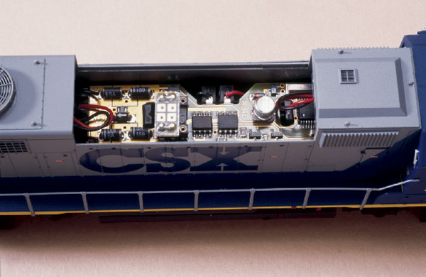
The Atlas Master dual-mode decoder is a circuit-board-style decoder measuring 11/16″ x 2 7/8″ x ¼” thick. It’s designed to be a drop-in replacement for most recent Atlas diesels, but is in no way limited to this use. I installed it in a Walthers F40PH by simply clipping all the leads from the trucks, bulbs, and motor, then attaching them to the appropriate pins on the decoder following the instructions.
The solderless connections are made by slipping the leads through holes in the circuit board and pushing plastic covers over them. There are ten pins on the decoder but strangely only four covers are supplied. If you’re replacing an existing circuit board, you’re probably okay (definitely if it’s an Atlas), but I had to improvise. I can’t see any reason not to supply a full complement of covers with the decoder.
The dual-mode decoder has a small plug mounted in a socket on top, and pulling this out and moving it over one row of holes changes the decoder from DCC to straight DC operation.
It took me about 15 minutes to set up the system, most of that stripping wire (not supplied) and screwing it to the terminals. Since I had the Commander and Generator before the decoder, I first tested it by plugging a Wangrow SH-154 decoder into an Atlas AEM7. Like all decoders, its default address is 03, so I pushed the “+” button until it read “L 3.” I pressed the “up” direction arrow, turned the control knob, and the engine started moving. The knob felt very smooth and gave fine control. I stopped the engine, hit the down arrow, and it took off in reverse.
Thrilled with this early success I proceeded to programming, which requires a separate track. This can be separate from the layout or it can be a siding or section of track insulated from the rest of the layout using a DPDT switch (or an Atlas Selector).
Once on the programming track, press both direction buttons at once and the display will read “Sch.” Press the “+” key and it will now read “Pro.” Press “enter” and it will read “R1.” This controls the locomotive address in Register Mode programming. Press “enter” again and it will read “u -.” You can now hit “+” until you get to the address you want. (Note: You can program the decoder to any address from 0 to 255, but the system will only control 0 to 99.) It can also read an address that’s already been programmed.
When I first tried programming the AEM7, I got an “Er 2” message on the display, which means the programming didn’t work. After some experimenting I called Atlas, and found out the problem is that the AEM7’s nine light bulbs put such a load on the decoder on the programming track that the Commander can’t read it. By temporarily disconnecting some of the lights I was able to program the unit just fine.
When installing the Atlas decoder in the Walthers F40 (with two bulbs) I had no problems. It should be noted that the problem arises because the amount of current an unpowered decoder can draw or that a command station must generate on the programming track wasn’t part of the National Model Railroad Association DCC standards, and similar problems have arisen with other systems.
Once you’ve programmed a few engines with different addresses you’ll want to move between them. You can simply scroll through all the addresses in order using the “+” and “-” keys to move up or down through them. However, the Atlas Commander also has a “stack” feature that allows you to move quickly between eight non-consecutive addresses. Also, holding down the direction key and hitting “-” will get you to the previous address used. You can then toggle between two engines by alternately hitting “+” and “-” while holding down a direction key. The stack feature is one item that sets the Atlas Master ahead of the competitors.
The Commander will control functions 0, 1, and 2: That’s one more than the MRC Command 2000 and two fewer than the Digitrax Genesis, the Atlas Master’s closest competitors.
I hooked the system up to a length of On3 track and tried it out with one of my steam engines equipped with a SoundTraxx DSD150 decoder. I scrolled to the address, turned the control, and it ran. I then pushed F2 and as expected the whistle blew. All of the Atlas Master function keys are latching, so to stop the whistle I had to hit F2 again.
I then tried to change the address and once again couldn’t. Like the AEM7, the DSD-150 overloaded the programmer. I tried a DSD-150 out of the package and could program it fine as long as no speaker was attached. In talking to Atlas and SoundTraxx we determined that there’s no problem using SoundTraxx’s newer drop-in circuit-board-style diesel sound decoders or the LC series steam and diesel decoders. As with the AEM7, the problem is not insurmountable, but it makes reprogramming a chore.
The newer SoundTraxx decoders are set up so that F1 controls the bell and F2 controls the whistle or horn. However the DSD-150 that I used has the bell controlled by F3. Thus, out of the package the only sound I could control was the whistle (the steam chuff worked as it’s not function controlled). You can, however, remap a SoundTraxx decoder to make any function number control the bell (or any other sound effect). To do this requires changing Configuration Variables (CVs) – in my case giving CV 35 a value of 16.
Nothing in the Atlas Master instructions mentions this, but besides Register Mode programming (which controls CVs 1-4, 7, 8, and 29) the Commander supports direct programming of CVs (assuming the decoder will permit it, and virtually all do). I stumbled on the secret to this but it is also explained on the Atlas Web site in a document on consisting. Go into program mode, click to R8, and hit “enter” twice so it reads the manufacturer. Now hit “exit,” which takes you back to R8, and hit “+” and the LED will read “c 9,” which is CV 9. You can now scroll through all 255 CVs. Remapping directions are available from SoundTraxx and decoder information for different brands will tell you how to use CVs to adjust speed tables, lighting, and other control features.
There’s an article on the Atlas Web site on putting locomotives into consists. You have to enter the lead locomotive’s address into CV 19 for the other locomotives. This does give you consisting, but it can only be done on the programming track, so is useful primarily for engines that you plan to keep together.
Besides locomotives, the Commander can also control accessory decoders.
Additional Commanders may be added by plugging them together with six-conductor telephone-style cable. The secondary units are programmed to operate in “slave” mode as described in the instructions. The communication system between Atlas components is Xpress Net, which is the same used by the newest Lenz components (no surprise, since Lenz built the system for Atlas). As such, many Lenz components will work with the Atlas system. For example, Lenz boosters (among others) can be used to handle larger layouts. Full information on using boosters should be on the Atlas Web site soon, but, if you need to know now, you can contact Atlas directly.
Although most people probably think DCC is only of value for larger layouts designed for multiple operators, the emergence of inexpensive systems such as this argues for its consideration even on the traditional 4 x 8-foot layout operated by one person. There’s no more having to park the extra engine on the one siding with a kill switch. Instead you can have several trains on the layout, not worry where they are, and switch among them by yourself.
As it exists, the Atlas Master is a complete, DCC system: power supply, controller, and decoder. However, it does leave what many will see as a critically important element of a DCC package: a walkaround throttle, which is in the “coming soon” category. Even with just the three elements now available, Atlas Master to me wins a price-versus-features comparison with other “beginner” DCC systems (MRC Command 2000 and Digitrax Genesis).
Moreover the Atlas Master system is fully expandable, putting Atlas in a position to introduce a broad range of DCC components and even more sophisticated controllers. In short, Atlas has stepped beyond its heritage of simplified controls to produce a control system on a par with its modern locomotives. Importantly, it has done without abandoning those modelers whose interest in electronics stops at the TV remote.
Prices: See product list
Manufacturer:
Atlas Model Railroad Co.
603 Sweetland Ave.
Hillside, NJ 07205
908-687-0880
www.atlasrr.com
dcc@atlasrr.com
Description:
Atlas Master DCC command station, power supply, and decoder
Product list:
330 Commander $149.95
332 System (Commander and
Generator), $179.95
335 Generator $39.95
340 Dual-mode decoder $29.95