


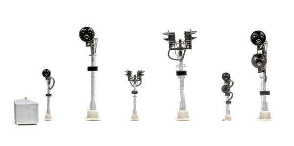
Although used on many railroads, the Type G was so common on the New York Central that it was sometimes referred to as an NYC-style signal. It’s still used today.
The single-head signal has one head with red, yellow, and green aspects. It’s used at the end of a block to indicate to following traffic that the block is occupied (red), a train has just exited a block and entered the next block (yellow), or the block is clear (green).
Bi-directional-head signals have two heads that face in opposite directions mounted on the same signal. These signals are used to guard the blocks from traffic moving from either direction.
Double-target signals are located at a turnout, such as at a passing siding. The top target controls the main line, and the bottom target governs the diverging route.
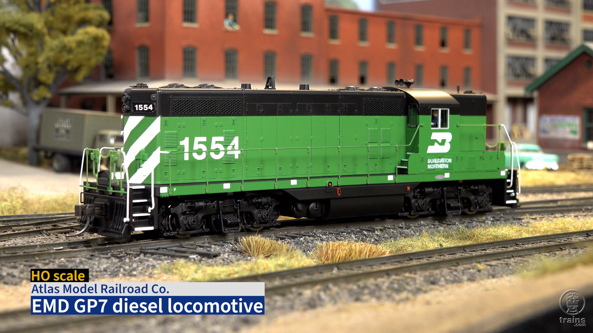
Each Atlas signal has a metal mast and plastic head, platform, ladder, and base. The signals feature great detailing, especially the in-scale, thin-profile ladders and platform. The base includes four mounting holes. A plastic bungalow is also included.
For bi-directional and double-head signals, you’ll need two SCBs and two BDBs for each signal. Atlas also recommends connecting a Custom Turnout Signal Controller, available from Custom Signals (www.customsignals.com), when installing a double-head signal.
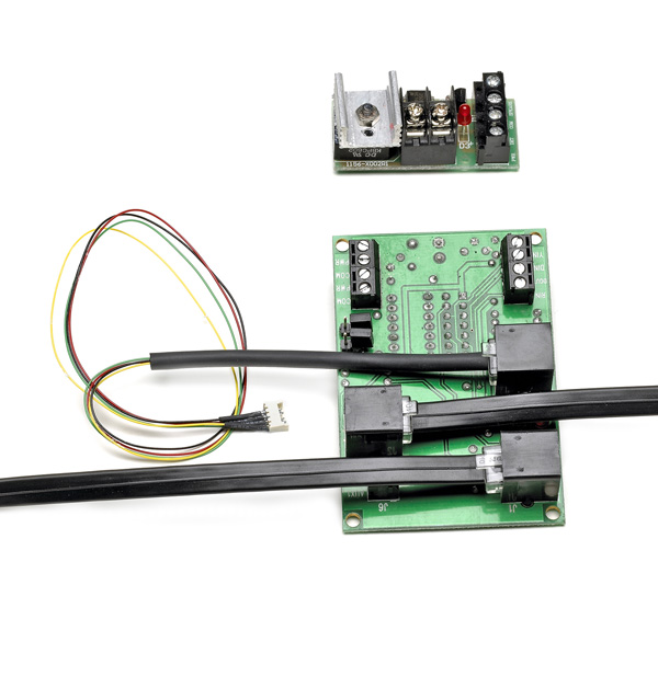
The Block Detector Board works by sensing current draw on an isolated section of track. That’s fine for a powered engine or lighted passenger car. A dummy engine or non-lighted car will need at least one resistor-equipped wheelset.
Basic installation of one signal is straightforward, following the provided wiring diagram. For one signal I used lengths of solid 22AWG red and black wire to connect to the screw terminals on the circuit boards. The SCB has two sets of PWR and COM terminals. One set connects the first signal and SCB to the power supply, and the other set connects to the BDB’s PWR and COM terminals. I connected the DIN input on the SCB to the DET input on the BDB.
Then I connected the BDB’s PWR IN terminal to the track power bus and the TO TRK ter-minal to the gapped rail by soldering a green 22AWG solid wire to the metal rail joiner at the center of the block. You could use terminal rail joiners instead.
Each circuit board has a light-emitting diode (LED) that lights if the board is wired correctly. After connecting the boards and power supplies, I attached the signal to the supplied jumper wire’s micro connector. I then plugged the jumper’s RJ-11 plug into a telephone-style jack (J3) on the SCB.
For more-realistic operation, the signals can be used in integrated operation. In this mode the yellow aspect is controlled by occupancy of the blocks behind or in front of the train, instead of a timer.
For this mode, the PWR and COM connections go to the PWR and COM connections of the next block signal’s SCB and so on. The BDB’s PWR and COM terminals are then connected directly to the auxiliary power supply.
For integrated signal operation, you can use Atlas signal cables, which have telephone-style connectors that link SCBs together. These cables are available in 7-, 15-, and 24-foot lengths and range in price from $3.95 to $10.95. I connected our test signals as per the instructions and found that they functioned correctly, with the yellow aspect of the first block turning green as soon as the train exited the second block.
The cables simplify installation. However, the SCB includes screw terminals for connecting SCBs without using the signal cables.
The SCB also has a DOUT connection for an LED or relay. It follows the input of the DIN connection to the BDB and activates the LED or relay when a block is occupied.
With the signals already wired for integrated operation, all I had to do was remove the jumper across the JP2 terminal on the SCB.
Wiring is more complicated for stand-alone approach-lit operation since the signal’s SCB would need to be connected to not only the BDB associated with its block but also to the BDBs for the blocks before and after it, using the SCB’s J6 and YIN terminals.
Although the Atlas signals require installing a few components, the extra effort will reward those who want a reliable, realistic signal system for their layout


PRICE?
Looking for occupancy detection information. How does it work?, What types are available?, What works best on a DC system?, How do you attach to the track? Is there a helpful reference manual available?
These signals are also used in NSW and the models are realistic. Now if they could manufacture operating semiphore signals, both upper and lower quadrant as well as somersault signals, what a bonus.
Doing N scale. I'm rather new to modeling but bought two signals and two boards to try; already had NCE detectors. The telephone type wire used to connect between signals for integrated op is rather stiff and expensive. Guess regular telephone wire will work if you do surgery and reverse the wires, as the telephone type are reversed. They are nice but the whole setup is rather expensive.
I have not purchased any of these signal as of yet. I am most interested in using these as a mainline upgrade for a new ( still on paper) layout.
still building layout and would like to get more info on this signal system
thanks for the info. i was looking at strating signaling system to my line and with this info i can be up. and run but with signals
i liked what nigel had to say about the system. this is very encouraging. i have yet to install this system, but in the coming months , i'm going to try it out. can relays be installed, to show on control board?
Sounds like a great system, but I have no use for Type G signals. Offering other signal types, such as searchlight, typical 3-light, etc. would go a long way toward selling these products, in my opinion.
This system is a good basis for even a lot more options such as direction sensing for crossing signals. tunnel occupancy and direction, etc. Some electrical specs on the inputs and outputs might help in home design of auxilliary circuits.
I hope they develop the line and offer some other choices in signals. The C&NW used a different style entirely.
I have only installed one at the moment but have a few to install later but I am very impressed with the one I have installed. I use a Point switch to change the signal through the signal module, I just ground the appropriate side with the switch. The detector unit grounds the signal module when it detects current normally. I just ground the unit with the point switch to show the appropriate signal for the point direction. Just realise there are several different options to buy these signals, there are options to but the signal alone, but I recommend the one that has the signal, the CPU module and the detector. It is good value compared to buying separately!
I use these signals on my norfolk southern section of my railroad. The detailing on these signals are excellent
The signals for the NYC is a great idea. I was wondering if the single target signals would work on the NYC signal towers that is still in use today.
If I were to use them I would put them on typical NYC towers for the realizum that will require them.
I have used one signal as a 6 months test for the 6' entrance track into one of my terminals….it works
fool-proof, never a failure, and easy hookup. Too bad its not the PRR position type signal….i'd have 8 or 9 more blocks…PS I'm still DC, with no plans for DCC yet.
Mike M
NJ
Why no semaphore signals- I model the NYC in the late 1940s and need this type of signal. thanks
I'm glad that Atlas has this easy to install system available. However, I had heard that it was not DCC compatible. Does Atlas support DCC operation? Or are there shorts that could occur somewhere within the DCC system? I have a Digitrax Zephyr system currently.
Thank you for any additional information.