The model comes fully assembled, wired, and ready to install on a layout. However, it’s not designed to function on its own; for working signals, you’ll need to hook it up to a signal driver circuit like those available from Circuitron, Logic Rail Technologies, CTI Electronics, or Digitrax. Model railroad signals can also be controlled by computer software, just like on the prototype. [See “Operating signals with user-friendly software” in the Oct. 2007 issue of Model Railroader. – Ed.]
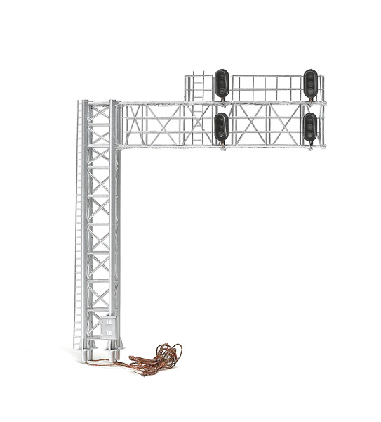
The model has four three-color signal heads, in the modern, single-hooded style, grouped in two pairs. The pairs face the same way, meaning that the bridge is designed to protect two tracks bound in the same direction, such as a two-track main line with dual crossovers.
In one case, the designers may have followed the prototype too accurately. The signal head pairs on the model are spaced 111/16″ apart. National Model Railroad Association (NMRA) standards for HO scale call for parallel tracks to be placed on 115/16″ centers, which when converted to full size is farther apart than is typical on the prototype. This means at least one of the signal head pairs on the model will not be centered above the right-hand rail, as is the prototype practice, unless you space your tracks closer than the NMRA recommends.
The only visible parts on the prototype missing from the model are the short lengths of 3″ conduit that guide the wiring from the horizontal spars to the vertical legs. Because in HO scale the horizontal members are far too small to put the wires inside, on the model they are instead strung beneath those members. This doesn’t look out of place, though. Since the wires are underneath the walkways and painted a matching aluminum color, they will be all but unnoticeable once the bridge is installed on a layout. The wires are routed inside the thicker vertical legs – one signal head per leg – a nice touch that makes keeping track of your wiring easier.
Each signal is powered by four wires: a cathode for each light-emitting diode (LED) and one common anode for all three LEDs. The anode wire is a different color from the others, but you’ll have to experiment to figure out which of the other wires is which. The LEDs in my sample model were bright when tested at the recommended 2.2 volts.
There are no installation or wiring instructions in the package. Since every signal controller circuit will be slightly different, the back of the box says to follow the wiring directions that come with your controller circuit. Also, even though the manufacturer sent me a drilling template for mounting the base on a layout, that should have been included in the package.
Except for the black signal heads, the model is painted a prototypical aluminum color appropriate for a new installation. You may wish to give your signal bridge a shot of Testor’s Dullcote or dust on some powdered pastels to represent accumulated dirt, corrosion, and diesel smoke.
The sample had only one notable defect: one of the horizontal spars on the lower walkway was slightly, but visibly, curved.
The company has plans to introduce single-mast, dual-head signals, as well as separate three-light heads for those wishing to customize their signal bridges.
With this modern cantilever signal bridge, BLMA has created a good-looking model that would be a realistic addition to the trackside scene of many HO scale railroads set in the 1990s or later.
Price: $89.95
Manufacturer:
BLMA Models
16623 Pear Blossom Ct.
Whittier, CA 90603
www.blmamodels.com
Description:
HO plastic and metal cantilever signal bridge


