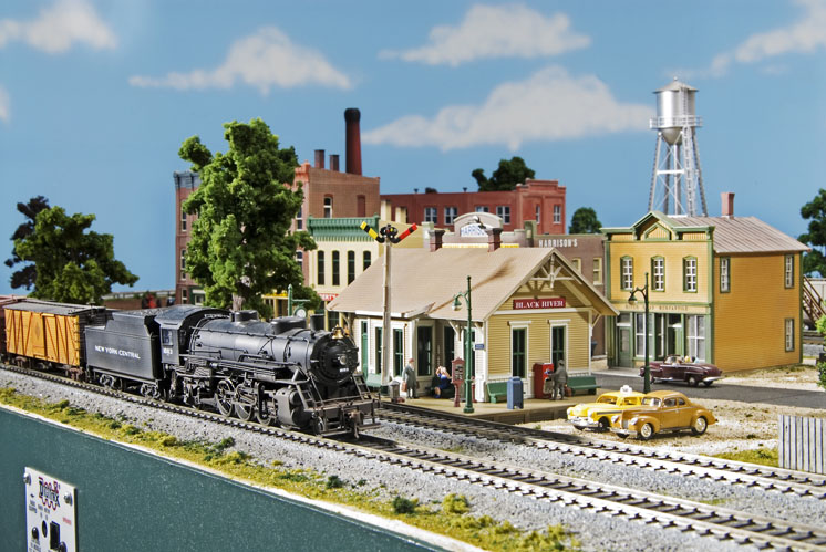
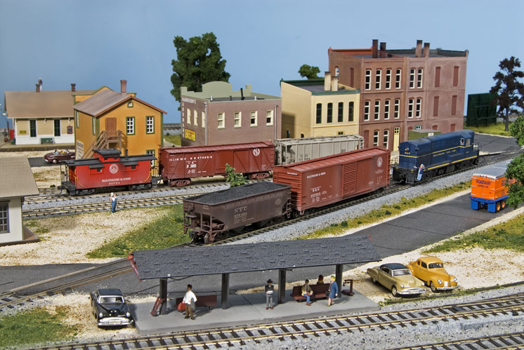
Building and operating a model railroad, whether it’s big, small, or somewhere in between, can be a lot of fun. And, with the wealth of easy-to-use track and scenery components and ready-to-run locomotives and cars available, building a good-looking layout has never been simpler or faster. Our HO scale Black River Junction project railroad is an example of what you can do with modern modeling products and techniques.
In building the 8 x 10-foot L-shaped layout, we used materials we felt would get things up and running quickly, as well as give good results. Our list included items such as Kato Unitrack with built-in roadbed, Woodland Scenics vinyl grass mats, assembled and partly assembled structures from various manufacturers, and a Digitrax plug-and-play Digital Command Control system. We built the benchwork using Jim Hediger’s lightweight all-plywood design, making the layout easy to transport or store if need be.
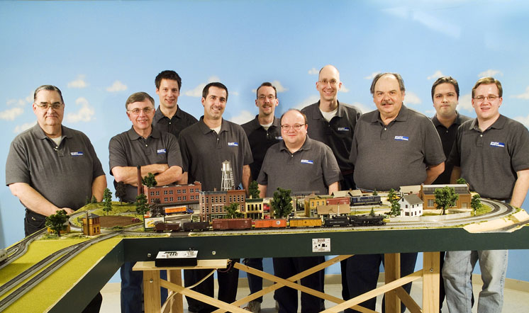
As with any project, we experienced a few trial-and-error moments along the way. Still, we think the Black River Junction RR was a great success. And with each member of the staff tackling a different part of the construction, we finished the railroad in just about four-and-a-half days.
If you’ve been waiting to get started on that first layout, this may be your opportunity. In the next few months, various MR staff members will explain how they helped build the Black River Junction, and we invite you to follow along. Who knows? One day you may be running trains on your own version.
Layout at a glance
Name: Black River Junction
Scale: HO (1:87.1)
Size: 4 x 8 feet with an 18″ x 72″ staging extension
Prototype: New York Central and Baltimore & Ohio RRs
Locale: Ohio
Era: 1950s
Style: freestanding
Mainline run: 24 feet
Minimum radius: 191⁄4″
Minimum turnout: no. 4
Maximum grade: none
Benchwork: tabletop
Height: 421⁄2″
Roadbed: Unitrack built-in roadbed on 1″ foam board
Track: Kato Unitrack
Scenery: foam insulation board and Woodland Scenics vinyl grass mat
Backdrop: none
Control: Digitrax Digital Command Control
Designed for two
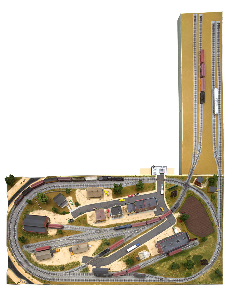
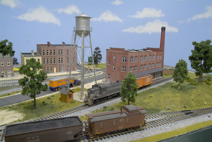
The Black River Junction depicts a fictional 1950s Ohio railroad town. It features a crossing and interchange point between the New York Central and the Baltimore & Ohio railroads, both of which had a presence in the Buckeye State. The layout’s NYC main line includes the town of Black River and the East Switch station, and it sees both passenger and freight trains. The long passing siding along the river is an ideal place to schedule meets.
Black River is also the terminus for B&O’s branch line. If you have more space, you may want to add a second crossing over the NYC at the river to continue the B&O’s route north.
The layout is designed to provide both mainline running and switching and features an interchange track. This is a connection point between two railroads, allowing them to transfer cars to each other. It’s really a universal industry since any type of car can be transferred between railroads.
In addition to switching, the layout has some passenger operation. There are passenger platforms at East Switch and Black River on the NYC, as well as the B&O’s depot by the interchange. We’ve chosen to represent passenger services on the NYC with a Budd RDC (Rail Diesel Car). On the B&O a single heavyweight combine and diesel engine suffice for branchline service.
To have a place for the trains to come on and off the main portion of the railroad, we’ve included an 18″ x 72″ removable staging table that stores underneath the main table when not in use. The staging yard has two tracks for each railroad, but you could add more staging tracks for each railroad.
An operating session on the Black River Junction will keep two people busy for more than an hour. During a typical session, the New York Central makes several scheduled passenger trips with the RDC and runs a local freight down the line to switch Hanson Products and the interchange. You can also run one or more through freights, which would have to thread their way around the scheduled RDC trips and over the crossing at the junction.
Black River is the terminus for the Baltimore & Ohio’s branch line. Therefore, the daily local would be a turn. This is a train that comes to town and then returns to its point of origin once its work is finished. The B&O turn enters Black River, does its switching and drops off cars for the interchange, then heads back to staging. You could also run a short daily passenger train on the B&O line. After stopping at the depot to unload passengers, the crew would then run the engine around the train for the return trip.
Now that you’ve learned a little about the layout’s design and operation, Jim Hediger will explain how he built the benchwork. Then, I’ll cover how we started the scenery.
Benchwork materials list
4 x 8 sheet 1⁄2″ plywood ripped into
13 31⁄2″ x 96″ strips (1)
4 x 8 sheets 1⁄4″ plywood (2)
8 foot 2 x 2 (1)
1⁄4″ x 1″ x 10′-0″ molding (2)
1⁄4″ x 3″ carriage bolts (2)
1⁄4″ x 2″ carriage bolts (3)
1⁄4″ washers (32)
1⁄4″ wing nuts (18)
1⁄4″ stop nuts (14)
Small box 4d 11⁄2″ bright finishing nails (1)
Small box 1″ panel board nails (1)
4 x 8 sheet 1″ foam insulation board (2)
4 x 8 sheet 1⁄8″ tempered hardboard ripped into 43⁄4″ x 96″ strips (1)
Adjustable furniture feet (6)
PL300 construction adhesive (4)
Carpenter’s wood glue (Titebond)
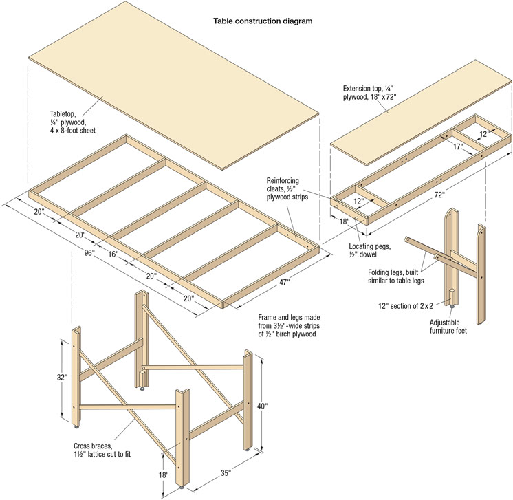
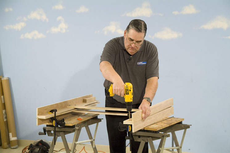
I built the benchwork for the Black River Junction using strips of 1⁄2″ birch plywood. Ordinary 1⁄2″ fir plywood has three or five layers of veneer, while the more costly birch plywood has seven layers, so it’s stronger. I used a table saw to cut the plywood into 31⁄2″ x 96″ strips to use in place of dimensional lumber. If you’re careful, one 4 x 8-foot sheet yields 13 8-foot strips, which is just sufficient for both tables and their leg assemblies. Smooth the edges of the cut strips with medium sandpaper to remove potential slivers.
Since we designed this layout for portability, I secured the joints with Titebond wood glue and 4d 11⁄2″ finishing nails. Ultimately, the glue provides the most strength – the nails secure the joints until the glue cures.
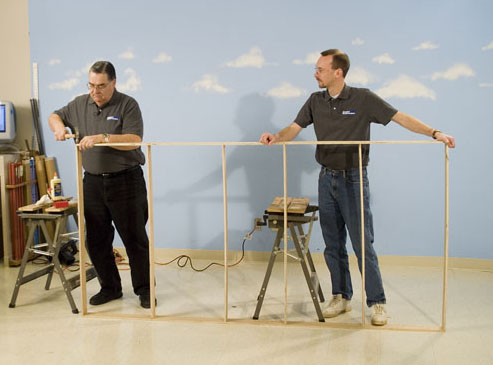
The main table consists of two long side rails and six 47″ crosspieces. Once attached, the side rails produce a frame width of 48″ to match the size of the plywood top. I used a square and marked the center lines for the crosspieces across both, spaced as shown in the drawing. I clamped one crosspiece vertically in a Black & Decker Workmate to help stabilize the piece while my “assistant” (David Popp) held the opposite end of a side rail. I applied a bead of glue, set the side rail in place, and drove two nails to hold the joint together. I then repeated this step at the opposite end and then for the remaining intermediate crosspieces.
David and I let the assembly dry for about a half-hour or so, and then we gently turned it over so the side rail was now flat on the floor with all the crosspieces sticking up. I added the second side rail, starting at one end with David holding the opposite end in alignment. I did the first end joint as before, but then I glued and nailed the crosspieces in order, finishing up with the opposite end.
The last step was to mark the crosspiece center lines on the sheet of ¼” fir plywood that would become the tabletop. We laid the framework on the floor and used the tile pattern to make sure the corners were square. I applied glue to the top edges of the frame, and then David and I carefully set the sheet of plywood on top with its edges aligned with the framework.
I put a few nails in one long edge and squared up the framework to match the plywood. Once the frame was square, we finished nailing the top in place, spacing the nails at 8″ to 10″ intervals along the frame.
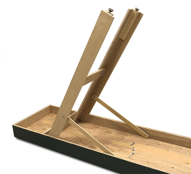
Each L-shaped leg is made from two 40″ plywood strips that I glued and nailed together. Next, I added a 35″-wide cross brace between each pair of legs. I turned the legs so the wide sides of the two legs faced inward, and then I glued and bolted the cross brace squarely between them to add stability.
To mount the legs, I drilled a ¼”-diameter hole into the tops of one set of legs. Then I clamped together both sets and drilled a matching set of holes in the second set. This makes them interchangeable for moves. I also added 8″ blocks of 2 x 2 to the bottom of each leg. After center- drilling these blocks, I added a leveling foot to each leg.
With the tabletop upside down on the floor, I clamped a set of legs to the first cross brace on each end, centered it, drilled the mounting holes, and bolted the legs in place. Then I drilled a ¼”-diameter hole through the side of each leg 32″ from the bottom.
I cut four side braces from strips of ¼” x 1″ wood molding, as shown in the drawing on page 53. I clamped and drilled all four of them at once for interchangeability. Then I rounded the ends so the braces fit inside the legs.
Yard extension
I used a similar construction technique for the extension, but I spaced its cross braces so the 17″-wide leg set could fold up underneath. To accomplish this, I mounted the legs with a single bolt through each side rail and rounded the leg tops for clearance. I also added a reinforcing block underneath the main table where the extension would be attached. The two table sections bolt together with a pair of ¼” x 3″ carriage bolts.
– Jim Hediger
Foam and vinyl grass mat base
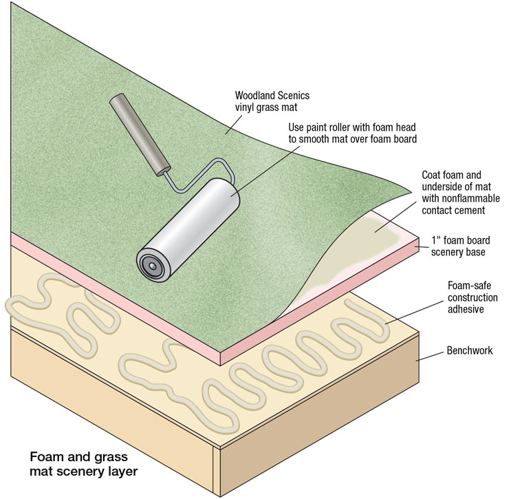
We used a layer of 1″ foam insulation board to make the layout’s scenery base. We covered the foam with a Woodland Scenics vinyl grass mat to jump start the scenery construction process. Later, after we had laid the track, we came back and added hills, roads, the river, grasses, and other scenic details to break up the uniformity of the vinyl mat.
We attached the vinyl mat to the foam first, and then we cemented the foam to the layout’s benchwork, as shown in the illustration. We used Weldwood Nonflammable Contact Cement to attach the vinyl mat to the scenery (Woodland Scenics also offers an adhesive.). When you use the cement, make sure you’re in an area with plenty of ventilation – its fumes are toxic. Simply brush or roll the contact cement on the back of the vinyl mat and on one side of the foam insulation board. Wait until the adhesive is dry to the touch but still tacky, and then join the two pieces.
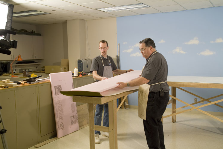
Contact cement isn’t very forgiving – once you touch the halves, it grabs and holds tightly. Because the vinyl mat is flexible, we found it was easiest to lay the mat flat on the benchwork tabletop and then lay the foam onto the mat. We started at one end and laid the foam onto the mat in a rolling motion. We then flipped over the mat-and-foam sandwich and, using small paint rollers with foam roller heads, we rolled out as many air bubbles as we could.
To cement the foam to the plywood tabletop, we used PL300 construction adhesive from Ohio Sealants (OSI). We then stacked about 30 years’ worth of Model Railroader bound volumes on top to hold the foam in place overnight while the adhesive set.
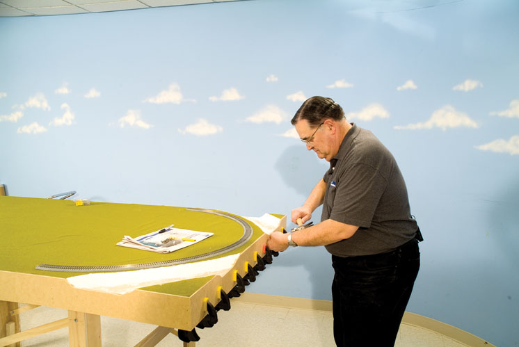
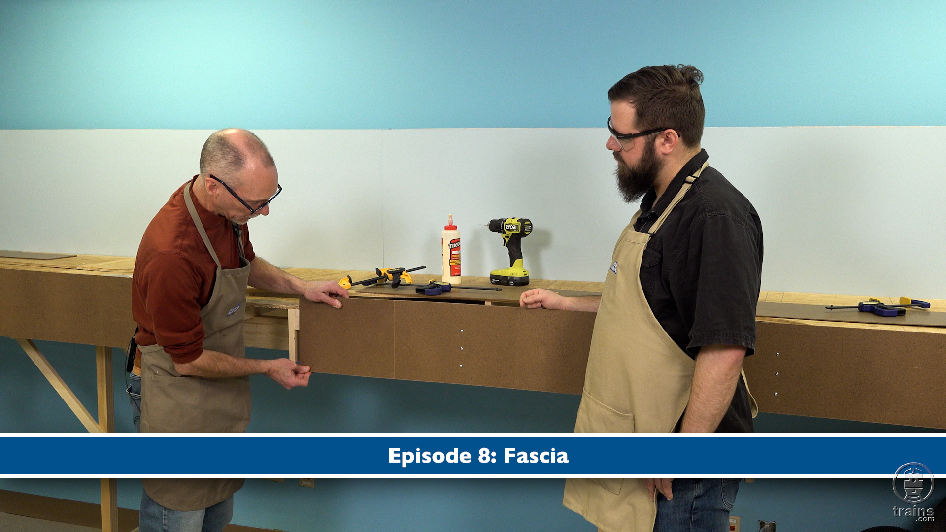
The final piece of benchwork construction was to add the fascia. After I’d cut the riverbeds (part 3 of this series, March 2007 MR), Jim and I cut 43⁄4″-wide strips of 1⁄8″ tempered hardboard to match the scenery contours of the layout.
Whew, that was a lot of work for the first day of our project, but we got it done on schedule. Next month we’ll look at some of Day 2’s activities, laying track, wiring the layout, and installing the DCC system so we can begin running trains.


