As I noted last month, in May 2008, my wife, Diana, and I took a post-retirement trip to Norway. We’d long wanted to visit the beautiful home of my ancestors, and the trip gave us the opportunity to renew our acquaintanceship with some Norwegian model railroading friends. Stener Harildstad was our host, chauffeur, and tour guide. We had first met him in 1984 when he attended Model Railroader’s 50th anniversary celebration in Milwaukee; he stayed with us then and has visited us on several other occasions. Stener models the Atchison, Topeka & Santa Fe and Union Pacific over Cajon Pass in N scale.
Not too long after we returned home, I got the call from Model Railroader magazine with the N scale layout proposal. Soon after that, I mentioned the project to Stener via e-mail. I noted that if he came to visit in the fall, he’d be welcome to help me build the layout; we set up a visit for early November.
I did a lot of doodling and planning. I used Kato’s track template, but the scale is small, so the resulting plans weren’t particularly accurate. In dealing with sectional track (Lionel, Atlas, and others), I’ve found that templates have their limitations. Nothing beats having sections of track you can lay down on plywood. Eventually, though, I came up with a pretty good sense of what the layout would look like.
General shape of the layout
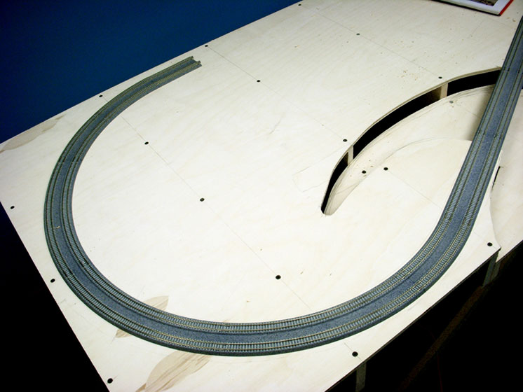
I started out with a box of Kato’s new N scale superelevated track, set V11, on a piece of 4 x 8 plywood on the floor. The basic curve diameter of the outside track (to the outside edge of the molded ballast) is approximately 3 feet. That left almost a foot of unused plywood along most of one side. It occurred to me that I might be able to cut off at least 4 feet of that edge and add it to the other end, extending the layout to 9 feet in length.
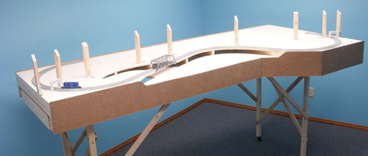
I knew that I wanted a through-truss bridge at some point, so I laid down a couple sections of straight track coming out of the curve at the left end. At the end of that I put in a curve heading back toward the right. A couple more short sections of straight followed by a left-hand curve brought the track close to the 4-foot edge and 9-foot length at the other end.
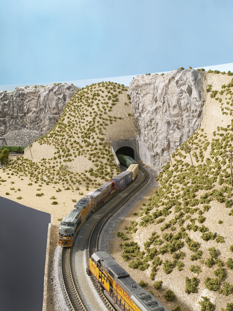
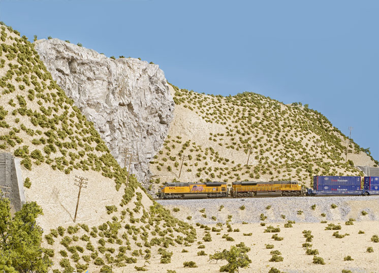
Unable to wait for legs and L girders and all other preliminary materials, I took one of Kato’s three-unit articulated well cars out of its box and put it on the track. In my mind’s eye, I was beginning to see Meadow Valley Wash in N scale.
What came next is definitely not a Model Railroader recommended practice. Without a detailed track plan, I took a leap of faith and declared the impromptu plan “good enough.”
What? Only half the plan is done! The easy half! Are you crazy?
Maybe, but I figured there had to be – at least I hoped there would be – a way to fit an intermodal yard, passing sidings, industrial spurs, and locomotive service tracks on the other side. Talk about a leap of faith!
Norski to the rescue
Lest you think I’m a really bad host, we didn’t work on the layout night and day. I did show Stener around. We toured Eau Claire, Wis. (my boyhood hometown), visited the twin ports of Duluth, Minn., and Superior, Wis., and stopped in Milwaukee to catch up with the MR staff and see the layouts.
In truth, however, we did spend a lot of time building benchwork. And I’m very grateful to have had Stener helping. Not only were his talents and ideas helpful, it’s just good to have companionship while you’re working.
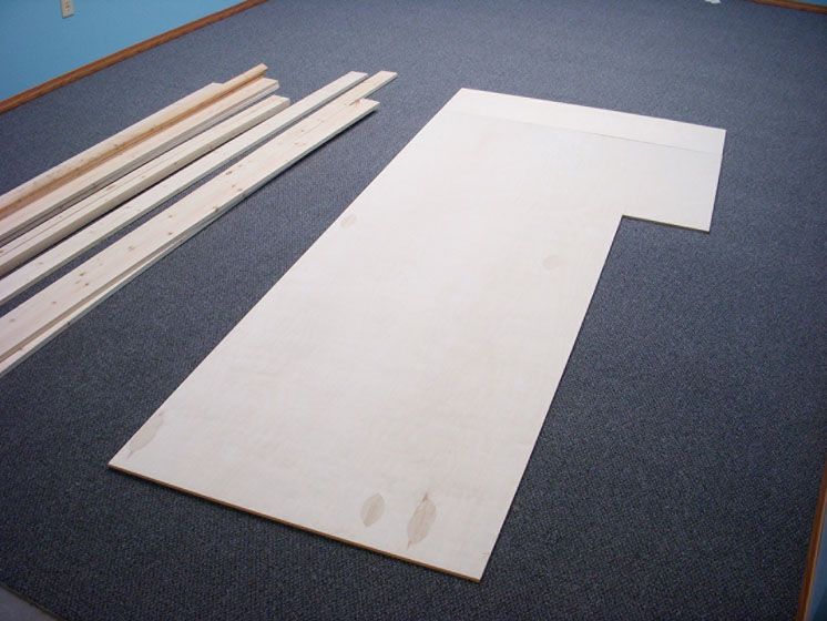
Our first step was to position the Meadow Valley Wash track on the 3⁄8″ plywood, using that to figure out where to cut the 12″ length of plywood – 5′-9″ gave us enough room for the final curve. When we turned that cut-off plywood 90 degrees, placed it at the wide end of the layout, and cut it off at 4 feet, as shown in fig. 1, we had 21″ of plywood left over (part of which I used later for the 7″ x 11″ control panel drawer). Now it was time to focus on the benchwork.
L-girder benchwork
L-girder benchwork is ideal for railroads with grades. There are no grades on this layout, and only Meadow Valley Wash would be below grade. However, one of the other advantages of L-girder benchwork is that it provides plenty of strength using a minimum amount of wood. One of my requirements was that the layout needed to be portable, and anything I could do to keep the weight down would be a good thing.
Rather than go into nut-and-bolt detail about L girders here, I recommend that you get a copy of Jeff Wilson’s Basic Model Railroad Benchwork (Kalmbach Publishing Co., 2002).
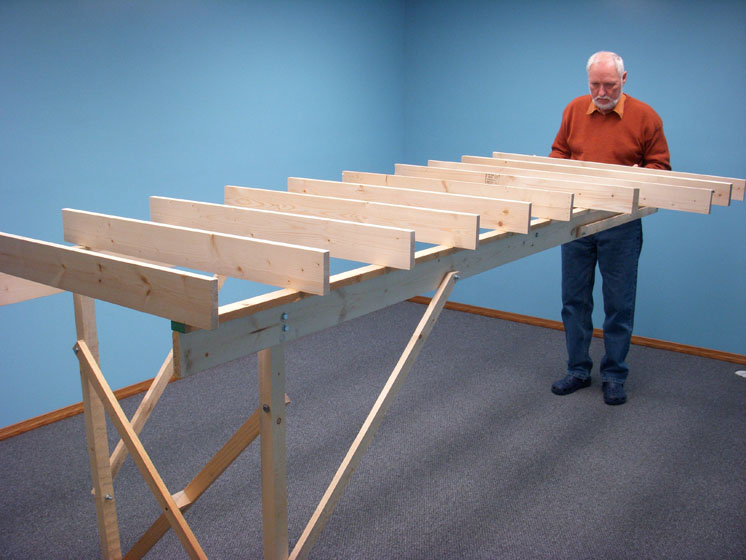
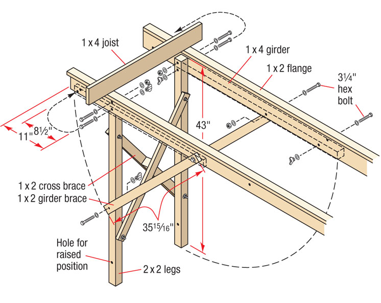
Step one is to build two L girders. We used 10-foot lengths of 1 x 4, with a 10-foot 1 x 2 for the flange. [A 1 x 3 is even better for a flange. – Ed.] We glued and nailed the two girders, rather than screwing them together.
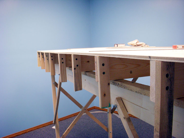
Each of the four legs is a 43″-long 2 x 2. I’m really happy with the resulting 50″ height of the layout (leg length, plus nominal 4″ stringers, plus 3⁄8″ plywood, and casters). I’m about 5′-10″ tall, and I found it to be a very comfortable height to work on, wire under, and watch trains pass by.
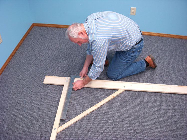
It’s important when you attach the legs to the L-girder that they’re square to the girder. See fig. 2. We used two 31⁄4″-long carriage bolts to attach each of the legs to the girders. Girder braces (1 x 2) attached with the leg square to the girder help keep the layout from swaying from end to end. Cross braces (1 x 2) keep the benchwork from swaying side to side, as shown in fig. 3. The girders are inset 4″ from each side of the plywood at the 3-foot end and run parallel the length of the layout.
Folding legs
The layout needed to be portable and, when completed, it needed to fit through a roughly 4-foot-wide door and rest in a 10-foot-long space (the back of the Kalmbach van). Stener, being an architect, is very handy with a pencil and rule. Together we figured out how the legs of the layout could be made so that they would fold up inside the benchwork.
There are eight bolts on the layout attached with wing nuts. We began at one end, removing the two wing nuts at the bottoms of the legs and pulling out the bolts. This allows the lengthwise angle braces to hang down. Then, with the same end supported (a person can hold it), we loosened the wing nuts at the tops of both legs and pulled out the bolts. With this end still supported, we swung the leg assembly up inside the girders and put the bolts from the top of the leg through holes drilled in the girders and the legs expressly for that purpose. Next, we swung the girder braces up and put the bolts through holes in the girders drilled to match the girder-brace holes in the legs. See fig. 3.
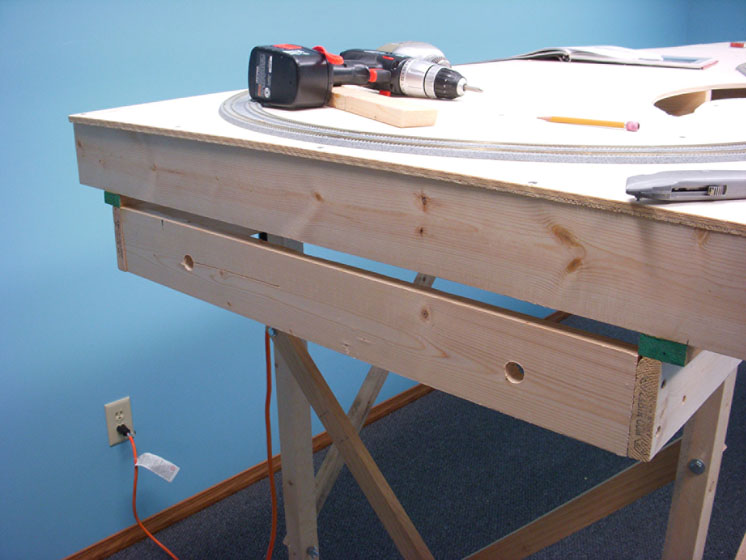
We followed the same procedure at the other end, and the layout was ready to move. We eventually made one modification to standard L-girder construction for the sake of portability. We added a length of 1 x 4 flush across each end between the girders and below the joists to serve as lifting points. See fig. 4.
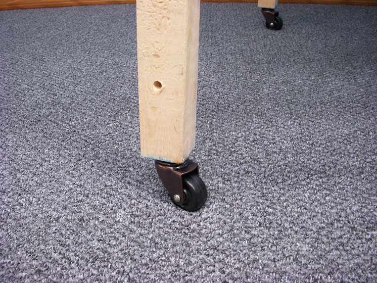
One of the best suggestions that MR’s managing editor David Popp gave me was to put casters on each leg, as seen in fig. 5. I’d already put in leveling bolts, but I followed his advice. The casters raised the layout another inch or so, but it made moving the layout much more convenient. I could whirl it around whenever I wanted to get a better angle, better light, or better position for photographs.
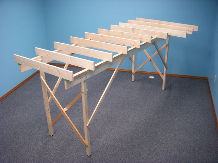
With the leg-and-girder assembly put together, we cut the joists and screwed them into the girder flanges. The 1 x 4s are the width of the plywood to which they will be attached, as shown in fig. 6. We doubled the joist under the plywood splice at the wide end so that both edges would have a firm support. See fig. 7.
After we had the benchwork built, Stener asked the logical, but previously unasked, question, “Can we get it out of the basement?” For one horrible moment I was sure we couldn’t. But then I realized that we’d simply need to tip it on one edge, carefully make an S curve through the workshop, and then guide it through the sliding glass door of my walk-out basement. From there we’d just turn it right-side-up, carry it around to the front yard, and put it in the van.
Meadow Valley Wash bed
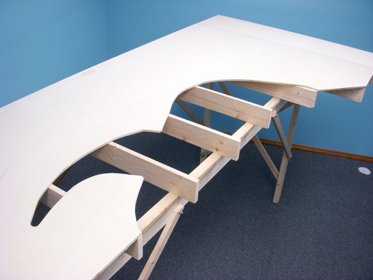
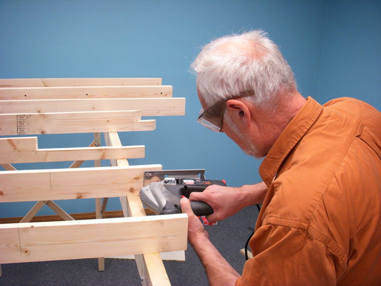
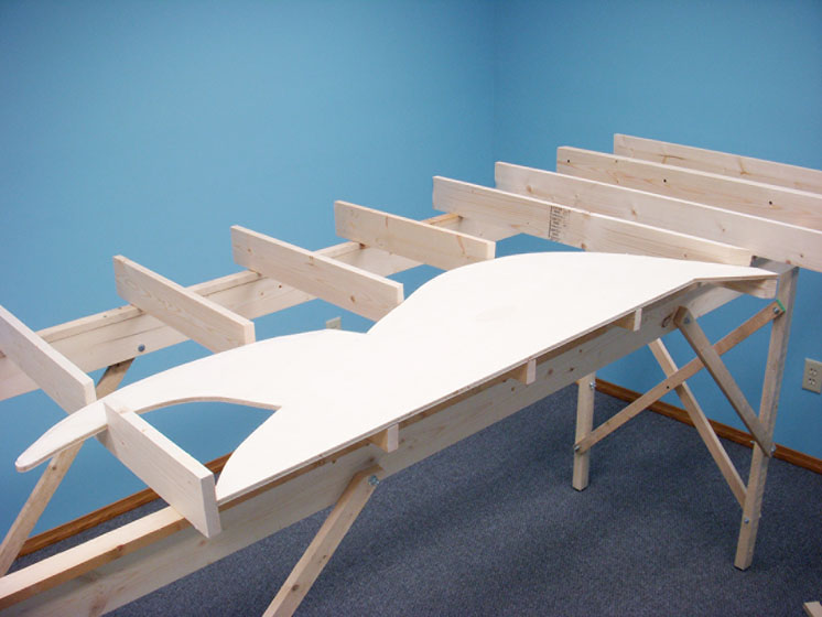
With the plywood sheet resting on the joists, Stener and I marked on the plywood where the track would be, where the wash at the end of the canyon would be, and where the creek would disappear between the canyon walls. Then we used a saber saw to cut out the base for the creek as shown in fig. 8. Next, Stener measured down 2″ from the tops of each of the appropriate joists and cut them with a saber saw. See fig. 9 at right. After adding a couple of supports here and there, we placed the plywood creek on the now-slimmer joists, as seen in fig. 10 on page 44.
With the plywood in place, we drew pencil lines across the plywood directly over each joist. As shown in fig. 11, we then drove 1″ drywall screws through the plywood into the joists.
Fancy fascia
Fascia, the flat edge trim attached to the side of most model railroads, is a beautiful thing. In addition to providing a place to attach bill boxes, town names, cup holders, and plug panels for walkaround control, fascia finishes a layout. The fascia has to be firmly mounted. Stener and I cut 7″ lengths of 1 x 2 and screwed them into the sides of each of the joists. See fig. 12.
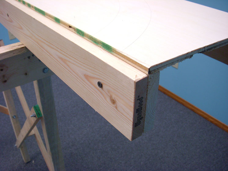
The fascia itself is 1⁄8″-thick tempered hardboard. We cut three 81⁄4″-wide lengths 8 feet long for the sides. We’d cut the ends later to roughly match the shape of the terrain. We used 3⁄4″-long Phillips roundhead screws to attach the fascia to the vertical supports previously attached to the joists, allowing about ¼” of the hardboard to extend above the top of the plywood. Two screws per joist sufficed. I considered using flathead screws that could be countersunk flush with the fascia. They would be less obtrusive, perhaps, but I was concerned that they might pull through the thin hardboard. See fig. 13.
Double-sided curved backdrop
There are a couple of ways to visually divide a layout, and Stener and I chose to run a double-sided, curved backdrop roughly down the center. On the Meadow Valley Wash side, the hills and steep bluffs could have pretty well divided the two sides of the layout by themselves, but I needed to hide the backs of the mountains.
We made the backdrop from tempered hardboard. L-girder benchwork lends itself well to adding a backdrop by allowing you to attach vertical supports to the joists. At this point on our layout, however, the joists were covered by plywood. Had we planned ahead, perhaps we could have cut the plywood in such a way as to allow us to drop supports to the joists, but we didn’t.
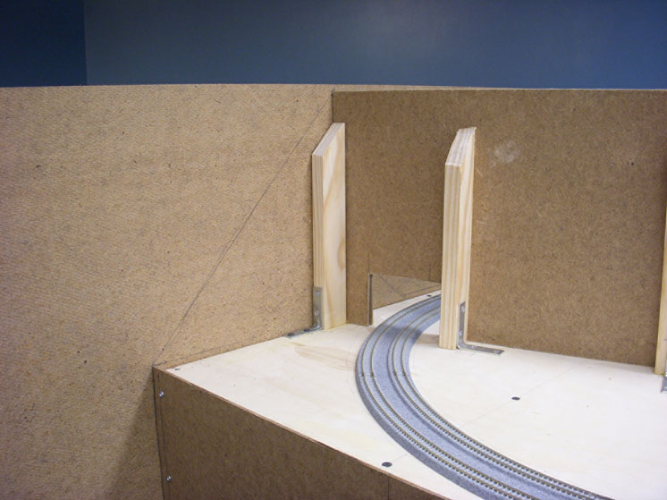
Instead, we used lengths of 10″-high 1 x 2 attached to the plywood with L-brackets at appropriate locations to support the backdrop. As you can see in fig. 14, we beveled the tops of the supports, angling them down toward the Meadow Valley Wash side, making it easier to cover them with scenery. The backdrop itself is attached to the yard side of the vertical supports.
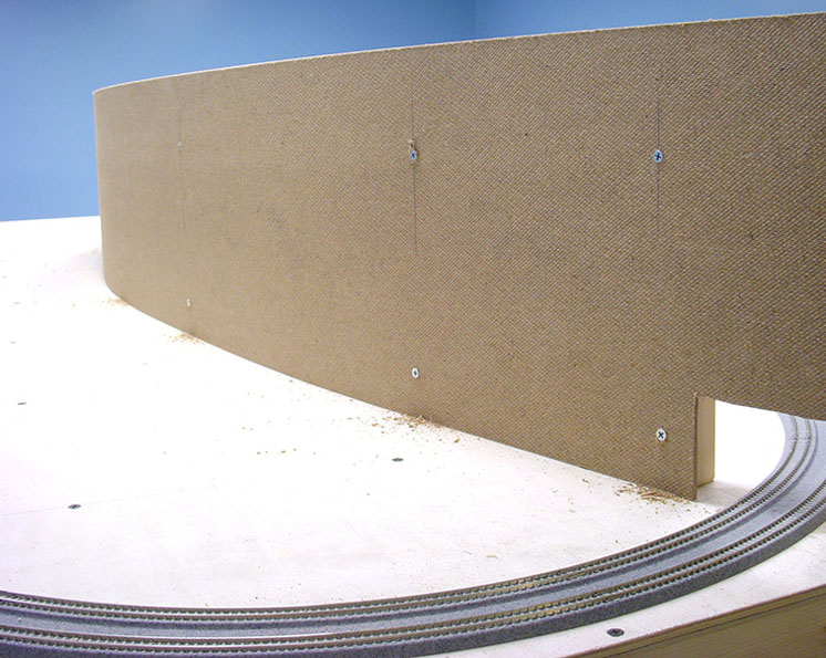
We cut three 1 x 8-foot strips of hardboard for the backdrop. The material we used is smooth only on one side, so we positioned one piece with the smooth side facing the supports. This provides a smooth surface for the couple of inches of sky that would show above the mountains on the Meadow Valley Wash side.
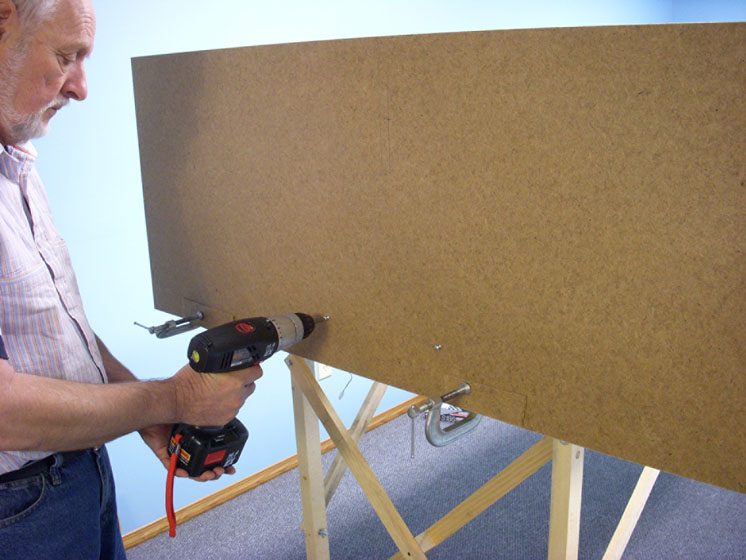
Next, we marked the backdrop to show where each of the supports would be, applied glue to the back of the supports, and then attached the hardboard using flathead screws carefully drawn down flush with the surface, as shown in fig. 15. The photo also shows how we cut openings for the tracks to pass between the scenes.
And since the entire backdrop needed to be more than 9 feet long, we ended up splicing another 18″ or so at the other end. We used additional supports at the splice point and at both edges of the tun-nel openings at both ends.
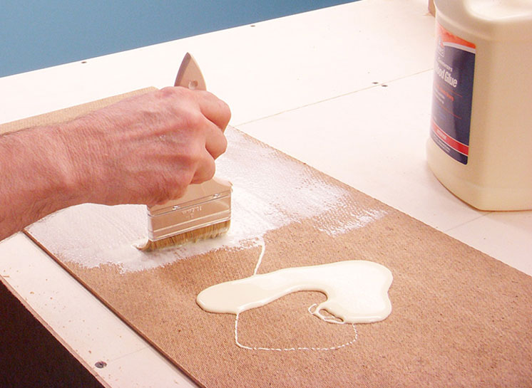
With one side of the backdrop firmly glued and screwed in place, we applied carpenter’s glue on the rough side of another length (having cut matching tunnel openings) and placed it against the backside of the hardboard already in place. See fig. 16. Note that we alternated ends for the splice.
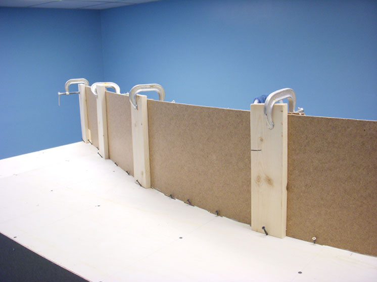
We used 1 x 4 scraps, shown in fig. 17, clamped at the top and screwed on an angle at the bottom to apply pressure as evenly as we could while the carpenter’s glue dried.
Once the glue dried, we removed the clamps. I sanded the joints on both sides of the backdrop and applied spackling compound. When that dried, I sanded the joint and it was ready for paint.
Fond farewell
Too soon it was time for Stener to bid farewell to the Salt Lake Route layout and head home to Oslo. I’m sure I could have muddled along and built benchwork on my own, but it was nice to have an extra pair of hands. I’ve continued to update Stener via e-mail on my progress, and he’s done a couple more sketches to more accurately reflect what the yard side looks like. But more on that later. From this point on, I was – for better or worse – pretty much on my own.


