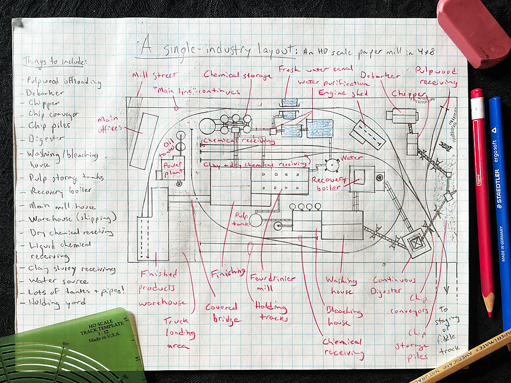
Modelers often compress industries to fit more of them on our model railroads. But doing the opposite – expanding a modeled industry to prototypical proportions – can create an intensely realistic operating experience that can’t be matched. Let’s explore that idea with a 4×8 HO scale paper mill layout.
Some industries are just too large and complex to selectively compress. For example, there’s the Post Cereals plant that was the topic of the article “Switching for Breakfast” in our annual special issue Model Railroad Planning 2014. I wrote an “Ask MR” post about it recently, including links to that article’s HO scale and N scale track plans.
When I decided to design my own one-industry layout for this article, I drew my inspiration from the paper mill in Chillicothe, Ohio, where I lived for a couple years in the early ‘90s. (This was also where I rediscovered model trains as an adult.) The biggest employer in the county was the paper mill simply called “The Mead.” The sprawling plant right in the heart of town was so big that in winter it generated its own weather phenomenon, which locals dubbed “Mead snow.” The plant is no longer owned by the Mead Corp., but it’s still there. A Google Maps view shows how massive and complex the modern paper industry is.
In order to know what all those train tracks are for, we have to learn a bit about what a paper mill does and how it does it. When I worked for the newspaper in Chillicothe, I had researched and drawn a graphic explaining the paper-making process, but that was more than 30 years ago. I lucked out, though, quickly coming across the website of Pixelle Specialty Solutions, the company that now operates The Mead. The site has a “Mill Tour” page, which includes a detailed graphic that puts my simple newspaper diagram to shame. (Right-click or CTRL-click on the image at top right on that page and select “Open image in new tab” to view it in full.) That let me put together a list of what structures and features I would need to include on my 4×8 HO scale paper mill layout.
And what a list it was! Pulpwood unloading tracks, log debarker, chipper, chip grader, chip conveyor, chip piles, digester, and on and on. Many model railroaders choose to model what’s known as a “pulp mill,” which makes its paper out of bales of dried paper pulp shipped in from other mills. You can go this route if you don’t have that much space to devote to the paper industry. But this cuts out about half the paper-making process and therefore about half of the operational and visual interest. The Chillicothe mill does the whole job from logs to paper, so that’s what I wanted to model.
The resulting track plan you see in my sketch is a little different from the usual 4×8. In addition to being focused on a single industry, it also has no continuous-operation connection. Although there’s a track representing a main line, it’s a dummy that leads off the edge of the table; everything on the table should be considered in-plant trackage. I don’t think the Chillicothe plant has a dedicated in-plant switcher, but for operations purposes I included an engine shed for one.
The structures and track arrangements on this layout are fairly generic. I used 18” curves and no. 5 turnouts, but didn’t follow the dimensions of any particular manufacturer’s products. Some of the track arrangements (like the crossover at center-right) would probably work best if hand-laid. Likewise, the structures I drew weren’t modeled on any particular kits (though Wm. K. Walthers does sell a few paper mill structures in HO and N scales). The most identifiable features of the industry should be the piles of wood chips, the towering digester, the tall stack of the recovery boiler, and the countless tanks, pipes, and conveyers connecting everything.
A paper mill like this would receive a wide variety of cars at its dozen-plus car spots: bulkhead flatcars of pulpwood, fuel oil (or, depending on your modeled era, coal) for the power plant, tanks of kaolin (a clay slurry used to polish glossy paper), bleaching compound, tanks of “white liquor” (a chemical used in the digester to break down the wood’s lignin), water-treatment chemicals, various granular and powdered chemicals used in the finishing process, and the occasional boxcar of replacement equipment. Finished products go out in plug-door boxcars dedicated to paper service with special linings to protect the lading from contamination.
Let’s look at the layout from the viewpoint of a crew working the plant. The train comes in from the staging track at lower right on my sketch. Pulling around the right side to the top of the layout, the crew then backs its train into the sorting tracks at bottom center, breaking it in two or three parts and storing the overflow on the power plant spur if necessary.
Hopefully the yardmaster blocked the train in an order that makes the plant easy to switch, since there’s a mix of facing-point and trailing-point spurs, and the only runaround track – in the chemical receiving area – holds no more than two or three cars. Shoving cars into the pulpwood receiving tracks at top right or the chemical spur at the bleaching house will require such a runaround maneuver. Delivering fuel to the power plant and switching the clay, dry chemical, and liquid chemical receiving tracks are far more straightforward tasks. The last task should be to pull loaded cars from the finished products warehouse, since the train can then head straight back out to staging.
If a 4×8 HO scale paper mill layout isn’t for you, there are plenty of other industries that could easily support the single-industry layout concept: steel mills, lumber mills, glass factories, meat-packing plants, auto assembly plants, even intermodal yards. Do a little research and you’ll find all kinds of interesting modeling topics.




Hi Steve,
I’m finding the “Sketching with Steve” pieces interesting. I am abandoning a much larger layout ( a real maintenance hog) in exchange for a smaller, more manageable one. The ideas you cover are helping my planning process. Thanks!
Lou Carreras