Use of hydrostatic lubricators
Proper lubrication of the valves and cylinders of early steam locomotives was an iffy proposition. Many depended on the water content of the low-pressure steam to do the work. It wasn’t satisfactory. It was complicated by the fact that these parts of the machinery were not easily accessible.
Primitive oil cups were devised, which required frequent attention and were not totally effective in delivering oil where it was needed against the pressure of the steam. There was also a problem with the lubricants of the day, which weren’t totally effective against the higher temperatures and pressure of the steam. The common “engine oil” was not effective; a better lubricant known as “valve oil” was created, which could withstand and be effective against the higher temperatures and pressures.
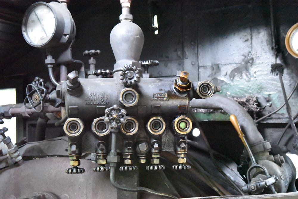
A device was created that forced oil under pressure through tubing to the valve chests and cylinders where it was needed. Called a “hydrostatic lubricator,” it was basically a tank located on the back head of the boiler which fed oil under boiler pressure to the points where it was needed. The lubricator worked by introducing a measured amount of water to the bottom of it. The water, being heavier than the oil, forced the oil through feeds in its top to tubing to valve chambers and even the air pump. The hydrostatic lubricator needed attention only two or three times during a run where the water could be drained out and the oil replenished — a relatively easy and quick chore, usually performed by the fireman.
Problems with hydrostatic lubricators
The inherent defect with the hydrostatic lubricator was that it delivered oil at the same rate to the machinery no matter how fast the locomotive was moving. It didn’t matter — 10 mph or 100 mph — the hydrostatic lubricator didn’t know the difference.
This problem was solved by the invention of a mechanical oiler or lubricator, linked to the locomotive’s machinery, usually to a part of the valve gear, which would pump faster as the speed increased. Not only that, but the mechanical lubricator could also be fitted with “auxiliary tanks” to hold enough oil to last for hundreds of miles. And not only valve oil was handled in this manner, but engine oil lubricators could also feed oil to other locations on the locomotive. Milwaukee Road’s 120-mph 4-6-4s lubricated their crosshead guides this way. Large locomotives might have three or even four lubricators (N&W’s class J 4-8-4 used three — one valve oil and two engine oil) with auxiliary tanks permitting the engine to go from Norfolk, Va., to Cincinnati, Ohio, some 600 miles, without attention.
This mysterious device is a little less mysterious now. Thank you.
The description of how the hydrostatic lubricator uses water to force oil to the outlets is a bit misleading, or perhaps incomplete. When the locomotive’s throttle is open, and the engine is being fed steam, a tiny bit of this steam enters the bell-shaped part of the casting at the top-center on the pictured unit. The steam condenses in this bell, and the created water settles to the bottom of the housing. The rising water level forces the oil thru the metering valves, and the “drip rate” is visible in the sight glasses at center. When the engineer shuts the throttle, the action slowly stops. This could be a problem on long downgrades, and a reason why a small amount of power might be applied while drifting, to maintain lubrication. When the water level gets too high, the fireman closes off the inlet valve, drains the water, and then re-fills the oil chamber, then opens the inlet valve and the process starts all over again. Locos that have their feed valves open too far can throw a lot of oil out the stack and quite a mess can result all over the boiler top and anything near the track!!