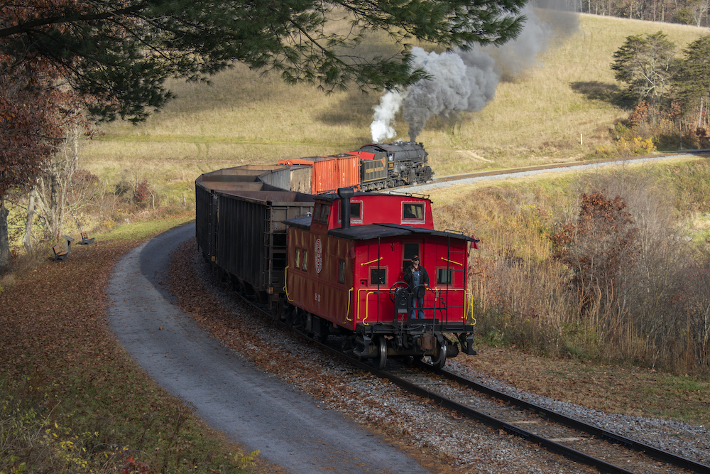
Given a choice, railroads will always follow a straight, level path. Trains use less energy, speeds are higher, and there’s less wear on equipment when railroads can build on an arrow-straight line. But land rises and falls, obstacles must be avoided, and this requires grades to compensate for changes in elevation and curves to reorient the direction of the tracks. Here’s how railroads design grades and curves.
Grades: uphill and down
In North America, gradient is expressed in terms of the number of feet of rise per 100 feet of horizontal distance. Two examples: if a track rises 1 foot over a distance of 100 feet, the gradient is said to be “1%;” a rise of 2 and-a-half feet would be a grade of “2.5%.” In other parts of the world gradients are expressed in terms of the horizontal distance required to achieve a 1-foot rise. This system would term the above examples “1 in 100” and “1 in 40,” respectively.
On main lines, grades are generally 1 percent or less, and grades steeper than about 2.2 percent are rare.
The steepest grade on a major railroad’s main track (as opposed to industrial spurs) was historically said to be on the Pennsylvania Railroad north of Madison, Ind. Now operated by short line Madison Railroad, the track rises 413 feet over a distance of 7012 feet – a 5.89% grade. The title for steepest main-line grade long rested with Norfolk Southern (and predecessor Southern Railway) for its 4.7-percent grade south of Saluda, N.C. With Saluda’s closing in 2002, BNSF’s 3.3-percent Raton Pass grade in New Mexico became the steepest main-line grade in North America.
The effect of grades on train operations is significant. For each percent of ascending grade, there is an additional resistance to constant-speed movement of 20 lbs. per ton of train. This compares with a resistance on level, straight track of about 5 lbs. per ton of train. A given locomotive, then, can haul only half the tonnage up a .25-percent grade that it can on the level. Descending grades carry their own penalties in the form of equipment wear and tear and increased fuel consumption.
The term “ruling grade” is used to describe the limiting grade between two terminals. It determines the maximum load that can be pulled over that portion of line by a given locomotive. The concept is analogous to that of the weakest link in a chain; no matter how many lesser grades a train can handle, if it can’t make the ruling grade, it won’t be able to complete the run.
A ruling grade is not necessarily the absolute steepest grade between two endpoints; it is assumed that trains will surmount certain steeper grades with momentum from descending grades or with the aid of helper locomotives.
For grades that are short relative to the total length of a train’s run, helper engines — extra locomotives added to the front, rear, or even middle of a train — are employed. While the superior power of diesel locomotives has eliminated many helper districts, dieselization has brought helpers for use on trains going downhill, where dynamic braking is used to control speed on the descent.
If a train cannot make a grade, and no helpers are available, it may have to “double the hill,” a practice in which the train is taken up the grade in two separate pieces. On some hills, “tripling” is necessary.
When a grade is steep enough to render the conventional “adhesion” system unworkable, a rack (or cog) or cable system may be used. Though there are some isolated examples, such alternative methods of negotiating hills are not found in the U.S. rail network.
Watch those curves
Railroad track is either “tangent” (straight) or curved.
Curves are best thought of as portions of circles. Curvature on railroads is not expressed in terms of radius, as it is on model layouts. (It would be impractical to strike such a large arc in the field.) Rather, it is given as the angle between two lines drawn from the center of the circle of which the curve is a part to two points on the circumference 100 feet apart. Since curve measurement is the description of an angle, the units used are the familiar ones from geometry class: degrees, minutes, and seconds. (Remember from geometry class that a circle contain 360 degrees.)
Curvature can be expressed in terms of the number of degrees traversed by 100 feet of track. For example, a relatively gentle 5-degree curve encompasses 5 degrees of a circle for each 100 feet of track; a sharper 15-degree curve covers 15 degrees in each 100 feet. The radius (distance from center point to edge) of a curve is obtained with the following conversion equation: radius in feet = 5729 divided by the degrees of curvature. This is known as the “arc” definition of curvature, which is normally used by highway designers.
Railroad designers use the “chord” definition of curvature, which is based on the degrees encompassed by a 100-foot line segment whose endpoints fall on the arc described by the curved track. An approximate method of determining curvature this way involves stretching a 62-foot-long string between two points on the inside face of the outer rail head. The number of inches between the center point of the string and the rail corresponds to the degrees of curvature: 1 inch equals 1 degree, 2 inches equals 2 degrees, and so on.
For the purposes of the casual observer, the difference between the arc and chord methods of measurement are small: the radius of a 15-degree arc-definition (highway) curve is approximately 382 feet, while the radius of a 15-degree chord-definition (railroad) curve is about 383 feet.
Curves of 1 or 2 degrees are the most common on mainline railroads; the sharpest curve a common four-axle diesel can take is about 20 degrees when coupled to other rolling stock, more than 40 degrees when by itself. Mountainous territory, however, generally dictates curves of 5 to 10 degrees, or even sharper. Branch lines and minor spurs may have an even greater number of sharper curves.
Just as grades impose additional resistance on trains, so do curves. However, wheel- and rail-wear are more significant (in terms of cost) than added fuel consumption. While it may seem that a long, gentle curve is preferable to a short, sharp one, the resistance is in fact the same as long as the central angle is the same, regardless of the radius.
In addition to reducing severe grades, many line relocations have reduction of total degrees of curvature as their goal.
Because of the resistance produced by curves, they pose an added difficulty when located on grades. To keep the combined resistance of grade and curve from overwhelming trains, grades are often “compensated” by being reduced on curves so resistance remains constant. A grade so treated would be termed, say, “1.7 percent, compensated.”
Curves are often used to avoid undesirably heavy grades. By stretching out a given rise in elevation over a longer distance of track, loops and horseshoe curves (among other, less extreme, examples) keep grades manageable.
An important feature of a railroad curve is the extent to which it is “superelevated,” or banked. To counteract centrifugal force as a train rounds a curve, the outer rail is raised to a higher level than the inner one. The difference in elevation between the two rails — called the “cross-level” – is how civil engineers measure superelevation. On main lines, the maximum difference in “cross-level” between the two rails can be as much as 6 inches, which is a superelevation good for 95 mph on a 1-degree curve, 45 mph on a 5-degree curve.
Since a train traversing a heavily superelevated curve at a relatively slow speed tends to cause excessive wear on the low rail, many railroads reduced curve superelevation when their passenger trains disappeared. This practice has worked against the reinstatement or speeding up of passenger service.
Curves aren’t just portions of circles with tangents at each end; instead, a smooth transition in the form of a spiral is used. In a spiral, curvature and superelevation are gradually increased until the amounts needed for the curve itself are reached. Spirals may be more than 600 feet long in high-speed territory.


Jerry Polanich, I have written a reply and tried to email same. I was informed the email address given was invalid. Please email me at woodsidemike3@gmail.com . Thanks endmrw0211251224
Thanks for this article–for once, some real substance! I’m an old math teacher and have been interested in these details of railroad engineering. I read about the method of using a string to estimate degrees of curvature once many years ago and have had no idea where to look for it since. As I was reading this article I was hoping it would be there, and there it was!
Now for a layman’s intro to the math behind easement spirals . . . .
For very small angles like the grades for trains the force turns out to be the slope, or in this case the percent grade, so 1% of 2,000 pounds is 20 pounds.
For the nerds, the force along an incline is the weight multiplied by the cosine of the angle of the incline. For very small angles the cosine is very nearly the rise over run, or slope. Since grades are given as percents it is a simple matter to just multiple the weight of the train by the percent grade.
I made a typo in the nerd section, it is supposed to say the weight multiplied by the SINE, not cosine. In fact, replace cosine with sine wherever it appears. It is late and I am half asleep, sorry, or as the kids say, “my bad.”
The use of 100 foot cords on curves corresponds with the length of an civil engineer’s measuring chain which was 100 feet long. This is different from the measuring chain used by land surveyors which was 66 feet long.
Civil engineers when surveying and when drawing up plans and maps would place an engineer’s stationing point every 100 feet. This why you will find valuation maps and such locating buildings, bridge abutments, roads, etc. at – by example – “sta.1234+56” meaning 56 feet beyond engineers station 1234 which was 123,400 feet from the starting point.
The 66 foot long surveyor’s chain goes back to 1620 England when it was introduced by Edmund Gunter — and so it was called Gunter’s Chain. 10 square chains equal one acre of land. 80 chains equal one mile. 20 chains equal a furlong. And this brings me to the measurement called a Rod which was 16.5 feet. Four Rods would equal one Chain. This will explain why some railroad right-of-ways were only 33′ wide instead of maybe 50 or 100 feet wide. Also why some public roads were once 66′ or 99′ wide. And remember the athletic track around your high school football field was 660 feet long — 1/8 of a mile.
Great information. Going to use some of it in one of a series of lessons I am preparing for a class at church. Under the heading of “CURRENT LIFE LESSONS FROM OLD STEAM ENGINES.”
I am having trouble understanding (I’m old) the ratio of impact of increasing grade percentages – to- decreasing weight movement up an incline. I’ve read other articles on this and, frankly, feel like I’m now dumber than I was before I started trying to figure this out.
Example: If a train can pull 50,000 lbs on a 0% grade. How much can it pull up a 1% grade? Or up the 4.7% SALUDA grade on the old SOUTHERN RR?
The article says, “A given locomotive, then, can haul only half the tonnage up a .25-percent grade that it can on the level.” “IF” (and that is a big “IF” … I do the math right that means the engine can’t pull itself over a 1% grade. ?)
If I’ve confused everybody who reads this… well… then I’m not alone.
Would appreciate any who would take on the challenge of trying to help me understand this.
In HIS NAME
neal
I’m looking for a retired Engineer with access to test track for American Railroad Co-generation to test its
new Renewable Energy concept.
Here are a few lines from the up graded, more efficient Design version of it sent to the USPO with a provisional filing date of 09/17/2018.
EXTERNAL AUTOMATED BRAKING SYSTEM FOR RAIL-BASED VEHICLES
Inventor: Jerry W. Polanich
BACKGROUND OF THE DISCLOSURE
TECHNICAL FIELD OF THE DISCLOSURE
[0001] The present embodiment relates in general to power generating systems
associated with rail vehicles and, in particular, to a railroad powered co-generation system and
related air compression hose to produce a large volume of compressed air, and even more
specifically to a system for slowing rail-based vehicles and converting linear kinetic energy at optimum
optimum locations along normal grade level track to provide macro pneumatic utility capacity quantities of energy.
There is probably no single industry on Earth that has anywhere near as large of a
direct and/or indirect impact on our daily economic lives than the energy industry. Nearly all of
modern society relies on energy, and while most is electric, the energy sources are myriad from
which modern industrial electricity is derived. One unexpected but highly functional source for
storing energy is compressed air.
At the same time, railroads and their tracks traverse 233,000 miles of territory in
the United States alone. They are also a major source of transportation for both people and goods
that connect cities to each other.
As noted in US Patent 10,079,524 granted to Jerry Polanich, it can be efficient
and economical to employ air compressors that do not require electrical energy for their
operation, particularly when that plurality of compressor units and related pipeline and storage
system is configured to receive its energy input from the mechanical forces exerted by passing lengths of time lengths of time and used for industrial purposes as well as electrical generation, there are
nevertheless further improvements to other aspects of the system needed.and used for industrial purposes as well as electrical generation, there are nevertheless further improvements to other aspects of the system needed.
While the ‘524 patent is based on the application of the first part of Newton’s 1st
law, there is a need to capitalize on the second part of the same law in order to further the pursuit
towards totally zero carbon emission, sustainable energy recovery and immediate storage
systems. Specifically, at the terminal end of the railroad lines described in the ‘524 patent,
kinetic energy of a fast-moving train must be reduced to substantially zero as the train comes to a
stop at a given station.
To minimize the limitations found in the existing systems and methods, and to
minimize other limitations that will be apparent upon the reading of this specification, the
preferred embodiment of the present invention provides a railroad powered co-generation system
and related air compression unit.
The system employs an external unique system to tap the kinetic energy of
moving trains and through Air Compression Hoses (ACHs) to slow and help stop trains or other
rail-based vehicles while generating compressed air in the process. The system preferably
displaces millions of cubic feet of compressed air which is then deposited immediately to storage
near the outskirts of cities as trains approach them. Cities can then tap the stored air on demand
for multiple uses including among others the servicing of air condition and refrigeration units
and moreover the production of electricity.
By operating remote controlled or automatic air pressure control valves, the air
pressure increase in those hoses produces resistance to the train’s wheels. When a train traverses
over the plurality of air compressed air hose sections that is the conduit to produce compressed
air flow in the plurality of pipelines. The compressed air is collected in ACHs having a
longitudinal length in line with the railroad track and as this occurs, the train is slowed by the
process. By bringing tons of mass weight force in motion to a full stop after full speed, Newton
applies M*A to its rolling mass weight formula, ½ M*V^2, version. Using check valves within
the ACH, the compressed air is trapped, and the kinetic energy required to bring the train to a
stop is converted to potential energy as the compressed air. At least one check valve is positioned
on each of the plurality of pipelines between two adjacent air compressor sections to assure the flow of air in a single direction. The compressed air forced to the air outlet of the energy
recovery system. When the train makes its departure from a station, those valves open fully to
allow the train to ramp up to speed quickly.
Since there is too much more information and many more details for what I’m calling a new Retro tech pneumatic Industry , you may request more by reaching me at my e-mail address: jerrypolanich@gmail.com.
Please state you interest, questions and share with me a profile of your history. I’m forming a TEAM and need
professional on it to apply for a number of very attractive and rapidly approaching grants. CalSeed is one that has an opening date of March 11th 2019.
The information presented above, has puzzled me for years. Since the time I started to build a model layout, and then when I re-started, in an effort to make it more realistic, I have wondered about grades and curves. Thank you for this information.
Wow !!!! Great info, I feel like I could build a rr now. What a fantastic job they did in 1868/69 with hand tools and mules going the country & Rockies!!!!!