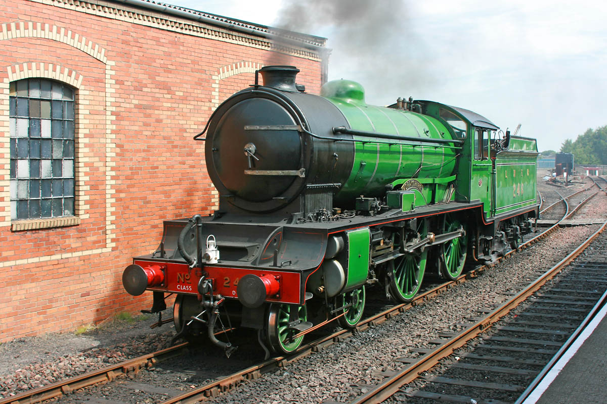
A Many British-built steam locomotives used a distinctive center-locking system, but some also had retaining clips around the smokebox door. The center-locking system was more complex to manufacture, but offered an airtight solution, preventing leaks that reduce the locomotive’s efficiency. In contrast, the U.S.-style clip system was simpler to operate, but more labor intensive to construct. So it was a trade off of simplicity in construction, but more ongoing maintenance in the British system, compared with more labor intensive construction with less operating efficiency using clips.
To remedy this, the British used a system of buffers between cars and locomotives to prevent the cars from crashing together. This gives such equipment a
distinctive look.
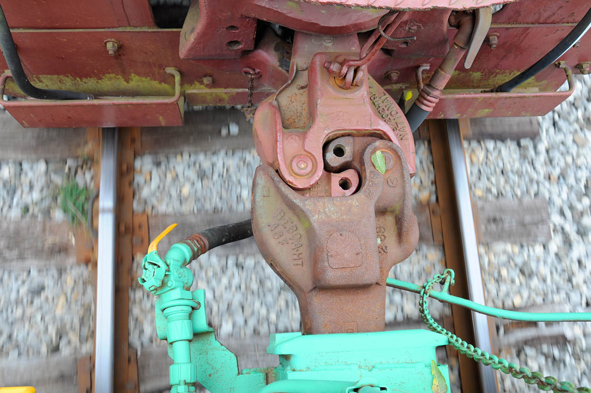
In the U.S., however, Eli Janney designed the first knuckle-type coupler and filed for a patent in 1873. That design forms the basis of most automatic couplers in use for freight around the world today.
The Federal Safety Appliance Act of 1893 forced the industry’s conversion to automatic couplers, which U.S. law required by 1898. This rule led to rapid widespread use and an 80 percent reduction in accidents involving couplers at the time.
The standard American knuckle coupler, known today as the AAR coupler after the Association of American Railroads trade group, is widely used around the world in the Americas, Africa, India, China, and Australia. Trains handling passengers and hazardous commodities use its variations.
Specialized automatic couplers are now used for heavy freight in Europe, and all modern multiple-unit passenger trains use some type of automatic coupler. These days such trains are often permanently coupled within the train-set using fixed steel tube connections, which are bolted together. This provides a more secure connection with reduced slack action, at the expense of operational flexibility. – Keith Fender






Strictly speaking, the type of coupling used in Britain and throughout much of Europe bears little resemblance to the link and pin coupler used in the United States prior to the invention of the Janney automatic coupler. The British device is more commonly referred to as a buffer and chain or buffer and screw coupler. Buffers are, of course, the spring loaded pistons on each corner of passenger carriages and goods wagons. The chain or screw coupler comprised large hooks on each carriage or wagon. One hook would have a chain with two links connected by a turnbuckle. After the engineman “buffers up” (moves the engine against the buffers of the standing carriage), a crewman goes between the carriages to loop the free link of the chain onto the hook of the opposite carriage. He then tightens the tunbuckle to eliminate any slack in the chain. Unlike the American link and pin coupler, no one need be in between the carriages when the engineman buffers up, as the final connection can be made after the movement has stopped, brakes set and it is safe for a crewman to go between.
Why do the British drain their cylinder cocks straight ahead? A lot of times, it makes the rail ahead of the engine wet and then the engine slips.
interesting, my grandfather was a brakeman and later conductor for Frisco RR and he lost part of his right index finger to the old link and pin coupler. That was a standard injury in those days.
I believe the British also stand to the side of the train and use a pole with a hook on the end to couple and uncouple the cars…